Linear Position Sensor Application Notes

Calibrating Alliance Sensor’s LVITs with SenSet™ Field Programmability


Please note that your LVIT sensor is calibrated at the factory to a specific measuring range.  You may choose to retain this calibration if it fits your purpose, or you may choose to recalibrate your sensor using the SenSet™ feature if you desire a more precise match of the sensor’s electrical output to your mechanical device’s range of movement.

Alliance Sensors’ LVIT Linear Position Sensors feature SenSet Field Programmability, which allows the installer to very simply and quickly match the full scale electrical output of a sensor to the actual mechanical range of movement of the device in which the sensor is installed. This type of activity is usually referred to as field calibration. To proceed with SenSet field calibration, follow these instructions:

1.  Install the sensor into your mechanical device, leaving the sensor’s I/Os unconnected.

2.  Connect the black wire or ground terminal to power (-), and then connect the correct DC power input (+) to the sensor via the red wire or + power terminal.

3a. To begin the SenSet process for voltage output, connect a DC voltmeter having an appropriate range with its plus (+) test lead connected to the green wire or output terminal, and the meter's (-) test lead connected to the black wire or ground 

 3b. To begin the SenSet process for current loop output, connect a DC milliammeter having an appropriate range with its plus (+) test lead connected to the green wire or output terminal and its minus (-) test lead connected to the loop load resistor, typically 250 or 500 Ohms. Connect the other end of the loop load resistor to the black wire or ground.

4.  Extend your mechanical device to the point of its full range of motion; then connect the white (cal) wire or cal terminal to the black wire or ground terminal for at least 3 seconds.

5.  Fully retract the mechanical device to its zero (start) position; then connect the white (cal) wire or cal terminal to the black wire or ground terminal for at least 3 seconds.

6. The sensor’s output will now be calibrated to the end points of your mechanical device.  The SenSet procedure can be redone without limit, but its operational range is limited to 20% of specified full range, both at zero and at full range. (0 to 20% around zero, and 80 to 100% around full range)  Note that both ends of the sensor’s range must be calibrated using the SenSet procedure for the process to take effect.

7. In the event of a problem, the sensor can be reset to its original state before SenSet was attempted by connecting the SenSet white wire or terminal to the black wire or ground terminal for at least 30 seconds.

8. When the SenSet process is complete, disconnect the voltmeter, or, in the case of current loop output, disconnect the milliammeter and reconnect the loop load to the green or output terminal.  If you are using a leaded or cable output sensor, you may wish to trim and insulate the end of the white (cal) wire to avoid an inadvertent recalibration.


     ME Series Linear Position Sensor Installed in a Hydraulic Cylinder


ME Series


Alliance Sensors Group offers in-cylinder position sensors to replace magnetostrictive technology at a lower installed and ownership costs. The LVIT ME series embedded sensor is placed in the same location as the other technologies as shown above. The sensor uses the gun drilled hole in the rod and piston assembly as the target. Typically a 10mm dia. hole is drilled but other sizes can be sensed. The unit is provided with a cable outlet for the electrical connections.    

     MR Series Linear Position Sensor port mounted in a Hydraulic Cylinder


MR Series


Alliance Sensors Group offers in-cylinder position sensors to replace magnetostrictive technology at a lower installed and ownership costs. The  LVIT MR series externally mounted sensor is placed in the same location as the other technologies as shown above. The sensor uses the gun drilled hole in the rod and piston assembly as the target. Typically a 10mm dia. hole is drilled but other sizes can be sensed. The unit is provided with a cable or connector outlet for the electrical connections.    


For more information contact our application engineering group at 856-727-0250 or send us a message by clicking here.

Bridge expansion and contraction due to seasonal heating and cooling is a common problem found in civil engineering. To combat this problem, engineers put expansion joints in the bridge to absorb these changes. This problem is compounded with railway bridges, where the expansion of a mile long section of rail could be as much as 4 ft over a temperature change in some climates of 100 degrees F. This could lead to rail buckling, known in the industry as “sun kink”, as shown below, and the derailment of a train.

Bridge Health

While improvements in steel tracks have evolved over the years, and prestressing techniques are used with rails and joints to help control the effects of expansion and contraction, many railway companies and mass transit agencies are taking the solution to the bridge expansion /contraction problem a step further by instrumenting the bridges themselves to find out how much the bridge has moved and to be able to determine if any structural problems exist or if any track shifting has actually taken place. By knowing that tracks have buckled or kinked, railway companies can divert trains and repair track problems before an incident takes place.

There are over 110,000 railroad bridges in North America alone, and each bridge is required to be inspected annually, but these inspections are done largely on a visual basis. Alliance Sensors Group's LV-45 series linear sensors are being used to measure bridge movements in systems like Metrom Rail's SafeStructure™ system for road and rail bridge monitoring, and as part of their SenTrack™ track monitoring system, both of which permit empirical data about the condition of rails and bridges to be tracked in real time.

The sensor's ability to survive the elements like high humidity, blowing snow, and driving rain over a wide range of temperature (-40 to 200 degrees F), as well as withstanding the inherent shocks and vibration from a train, makes this position sensor the ideal solution for such applications. Its housing is rated IP67 and is offered with various connector and cable terminations to suit virtually any environment.

Bridge Health 2

As can be seen in the photo above showing a pier-to-bridge interface measurement application, the LV-45s are hard fixed to the pier and to the bridge, using ball joint swivel rod ends to take up any misalignment during initial installation. The system can measure position changes in all three axes and can track those changes over time to show short and long term trends and highlight potential problems or incipient failures before they take place.

An ongoing challenge in the USA is that our transportation infrastructure is aging, as attested to by the increasing traffic and the resulting load limits being placed on bridges. In the present technological world, bridge monitoring does not have to rely on periodic human inspections, but could rely instead on electronically monitoring a bridge’s health, so it can be maintained and repaired well before any structural integrity problem could develop.

Bridge Health 1


Civil engineers who have the responsibility of keeping the infrastructure sound are becoming aware of sensor products available that could aid them in evaluating infrastructure condition. In a relatively short period of time, the cost of instrumenting a typical bridge can offset the cost of periodically sending an experienced inspection crew to that bridge. Alliance Sensors Group's LV-45 series linear position sensors are an important part of Metrom Rail LLC's SafeStructure™ system that can monitor important structural elements of bridges and transmit data to a remote information collection system in real time. These sensors are rated IEC IP67, and have built-in electronics that can operate over the wide temperature ranges found in the blustery winters of the northern reaches of the US, the dry, hot summers of the southwest, and the hot and humid conditions of the southeast.

Bridge Health 2


In the picture above, two position sensors are attached to the bridge and its supporting pier with rod-eye swivel ends to allow them to measure movement of the bridge over all three axes relative to the pier over time and ambient temperature. The LV-45 sensor is offered with either aluminum or stainless steel housings, a variety of mounting hardware, and cable or connector electrical terminations. These sensors give an analog output of either a high-level DC voltage or a 4-20 mA current loop, either of which can easily connect to any data acquisition system for continuous monitoring and/or data transmission over a remotely accessible wireless network.


Mechanical installation: MR-7 In-cylinder position sensors are designed to be inserted into an o-ring port machined into the rear endcap of the hydraulic cylinder.  Standard MR-7s use an SAE J1926-1 -8 port with a 3/4-16 UNF thread. Metric threaded versions use an ISO 1649-1 port with a M18 x 1.5 thread. Both ports are Illustrated below.  For either size port, the sensor's male thread comes with a Viton o-ring installed.

SAE J1926-1  -8 Port

MR-7 Series

ISO 1649-1 M18 Port

MR-7 Series


Before insertion of the sensor, the cylinder rod must have a 5/16-inch (8 mm) diameter (minimum) blind hole gun-drilled into it from the piston end that is at least 1 inch deeper than the nominal measuring range of the sensor. Ensure that the material of the cylinder rod is specified to ASG for proper calibration.

If the mechanical details are correct, the cylinder rod should be moved to its fully retracted position. The sensor may then be inserted into the o-ring port and tightened down with a wrench on its hex.

Electrical connections: Connect MR-7 sensors to the electrical system according to the following charts:

 4-Conductor Cable

I/O Function

Cable Color

+DC Voltage input

Red

Ground

Black

Analog output

Green

SenSet™

White

 5- Pin M-12 Connector

Cable

I/O Function

 Pin

Color *

+DC Power input

1

Brown

Ground

2

White

Voltage output

3

Blue

Current output

4

Black

SenSet™

5

Grey

*Cable colors shown are for industry

standard M-12 cord set mating plugs


SenSet: Instructions for the SenSet™ procedure can be found on here. If the SenSet feature is not being used, trim and insulate the end of the SenSet wire or cut it off completely.


Mechanical installation: An ASG ME-7 in-cylinder position sensors is embedded into a 48 mm diameter
cavity in the rear endcap of a hydraulic cylinder. It may be inserted from the front of an unassembled
cylinder or from the rear of a cylinder with a two-piece endcap with a separate end cover.
 
 
Front Install ME Series


ME Series Rear Install


As the drawing shows, the sensor is retained in the endcap with three set screws 120 degrees apart that
fit the groove on the sensor, or with a retaining ring inserted next to the mounted sensor body. Besides
clearance for the sensor's back and an exit hole for the I/O cable, there is also a clearance zone of 1 inch
(25 mm) diameter by 1 inch (25 mm) long required for the front nose of the sensor body body.
Before inserting the sensor, verify that the cylinder rod has a 5/16-inch (8 mm) diameter (or larger) blind
hole that is at least 1 inch deeper than the nominal measuring range of the sensor. Make sure that the
material of the cylinder rod is specified to ASG for proper calibration.
If the mechanical details are correct, the sensor may be inserted into the 48 mm cavity, being careful not
to nick the o-ring, and with the I/O cable routed through its exit hole. Fasten the sensor in place with the
3 set screws or a retaining ring.
 
Electrical installation: Connect ME-7 sensors to the electrical system according to the following chart:
 
ME-7 4- Conductor Cable
I/O Function  Color
+DC power input  Red
Ground  Black
Analog output  Green
SenSet™  White
 
 
SenSet: instructions for the SenSet™ procedure can be found here.
If the SenSet feature is not being used, trim and insulate the end of the white wire or cut it off completely.


Alliance Sensors Group, a division of H.G. Schaevitz, LLC, has developed a linear position sensing technology called LVIT that offers an excellent price-to-performance ratio compared to other linear position sensing technologies such as LVDTs, linear potentiometers, and magnetostrictive devices. Furthermore, LVITs can offer the best stroke-to-length ratio of any contactless linear position sensor, because their overall length only increases by a relatively small percentage beyond their stroke.

View Most Commonly Used LVITs Here! 

View Most Commonly Used In-Cylinder Position Sensors Here! 


So, the answer to the title question: What's So Good About LVIT Technology is summarized as follows:


- Excellent price-performance ratio compared to other common linear position sensors 

- Superior stroke-to-length ratio compared to other contactless linear position sensors 

- Contactless, frictionless operation with no components to wear out and no ring magnet

- Extremely robust to environments as a result of ruggedized construction and materials

- Many sensor sizes and configurations for different position sensing applications

- Pressure sealed sensors for fluid power applications, including in-cylinder position

- Less expensive than LDTs and more reliable than in-cylinder potentiometers


LVIT Linear Position Sensors

To find out more about this technology read on below. 


Block Diagram LVIT Linear Position Sensor


Block Diagram of Major Operating Features

The acronym LVIT stands for Linear Variable Inductance Transducer. Because LVITs are inductive, they are contactless devices with no friction issues or moving parts that can wear out. As is common for inductive sensors, they exhibit outstanding repeatability, with resolution limited only by the electronics used with them. LVITs offer the performance of contactless sensors like LVDTs or magnetostrictive sensors at a price comparable to industrial grade linear potentiometers.

They are DC in-DC-out sensors constructed with built-in smart electronics that has relatively low power consumption, typically much less than one watt. Because the basic sensor of an LVIT is extremely repeatable, an on-board microprocessor can be used to linearize the sensor's output signal and apply temperature compensation to the system using a built-in temperature sensor. This linearization process yields typical linearity errors of ≤ 0.1% of Full Scale Output (FSO), depending on the number of data points used for the sensor's calibration.

An LVIT sensor uses a long, small-diameter probe coil that is connected into the resonant tank circuit of an oscillator in the built-in electronics. A conductive tube moved over the coil changes its inductance and the resonant frequency of the tank circuit. Oscillator output is coupled to a 12-bit microprocessor in the on-board electronics to measure its frequency. The digital output of the microprocessor then goes to a digital-to-analog converter which develops a voltage proportional to frequency that is conditioned to produce a high level analog DC output from the sensor. The 12-bit microprocessor also determines the resolution of an ASG LVIT position sensor, which is 0.025% of FSO.

One reason for the robustness of LVITs is that the probe coil is wound on a glass-filled thermosetting plastic rod which can survive large deflections without fracturing. Its single coil winding makes only two connections with the electronics, which substantially reduces the likelihood of a failure and enhances reliability. The built-in electronics is completely potted within its housing, so these sensors can sustain high shock and vibration levels. This robustness, coupled with a normal operating temperature range of -20 to 85 C, and an extended operating temperature range of -40 to 105 C, permits an ASG LVIT to function very well in practically any industrial or commercial environment. In special cases where an LVIT might be required to operate in a higher temperature environment, the sensor's electronics may be located in a more benign environment a short distance away from the sensor's probe assembly.

Another reason for an LVITs' robustness is that the sensors' housings are made of heavy wall anodized aluminum or stainless steel and are environmentally sealed to IEC IP-67 or IP-68. The LVITs' operating rods (spoilers) are also stainless steel, and do not easily bend as happens with some other sensors.

ASG offers several series of LVITs with industrial duty housings and operating rods having swivel rod ends for use in typical factory automation applications such as packaging machinery, gates for sorting chutes, press brakes, and automatic assembly test stands. Other series of LVITs are offered with extra heavy duty housings to operate in such severe environments as mining machinery, off-road equipment, rail or road bridge motion monitoring, road construction equipment, snow plows, and garbage haulers.

Still other configurations available from ASG include sensors specifically made for operation to 5000 psig in hydraulic cylinders, either for port mounting externally or for embedding internally in the cylinder. For these in-cylinder applications, the cylinder rod or ram is gun-drilled with a hole in clearance of the probe coil, which then becomes the spoiler tube for the sensor. There is no need to machine a cavity in the piston for the magnet of a magnetostrictive device or for the spool of an in-cylinder potentiometer.

Besides the LVIT sensors for use in hydraulic cylinders, other pressurized sensors can be built for subsea applications at depths of 12,000 feet in a PBOF environment. There are also short stroke LVITs that operate in a pressurized fluid environment to provide spool position feedback in two-stage electro-hydraulic proportional or servo valves. In this application, the LVIT probe goes into a blind hole in one end of the main spool, which greatly simplifies installation and eliminates any need to mechanically couple a position sensor to the spool.

One valuable feature built into ASG LVITs is a proprietary process called SenSet; which gives a user the ability to match the end points of the sensor's analog output with the ends of the range of motion of a workpiece or the ram of a hydraulic cylinder to which the sensor is attached. This SenSet™ feature permits a user to optimize the position measuring system's resolution over its full range of motion.

ASG LVITs are offered with various connector or cable terminations in axial or radial configurations and can measure full ranges from fractions of an inch to 40 inches, with a resolution of 0.025% of full scale output. Operating from DC power inputs of 5 to 24 Volts, standard LVIT analog outputs include several high level DC voltages and 4-20 mA DC sourcing. Being digital devices, LVIT dynamic responses are shown as update rates, which nominally range from 250 to 500 Hz, depending on the LVIT series.

View Most Commonly Used LVITs Here! 

View Most Commonly Used In-Cylinder Position Sensors Here! 


There has been a revolution in the position sensor market with the development of low cost, high precision, inductive LVIT Technology developed by H. G. Schaevitz LLC dba Alliance Sensors Group in Moorestown, NJ.

LVIT Technology has significant advantages over LVDTs and Potentiometers having an excellent stroke-to-length ratio and using contactless, inductive technology; giving you best of all worlds at a cost-effective price. The LRS-18 series are designed for dimension or position measuring applications in factory automation and in various industrial and commercial applications such as automotive testing, mil/aero test stands, robotic arms, and packaging equipment.

LRS-18 Cutaway


The new LRS-18 series of spring loaded LVITs have the following features:

-  EXCELLENT stroke-to-length ratio

-  Contactless operation

-  Ranges from 12.5 to 100 mm (0.5 to 4.0 inches)

-  M18 x 1 threaded housing

-  IP67 sealed

-  Corrosion resistant, anodized aluminum or stainless steel body

-  Connector or cable terminations

-  A variety of analog I/Os

-  SenSet™ field programmability


The LRS-18 was designed with a focus on automation machinery and is constructed with an industry standard M12 connector and a M18 threaded body complimented by a spring loaded, stainless steel probe shaft in an ultra-high wear bearing system with a contactless inductive sensing coil connected to microprocessor based electronics, encased in a corrosion resistant housing.


Most snow plows utilize hydraulic actuators to raise and lower the plow blade, change the blade’s left-to-right surface contact angle, and adjust the plow blade’s front-to-back tilt angle. Typically, these plow positioning functions are under the plow operator’s control. However, the operator’s productivity can be improved and plow maintenance reduced if plow position feedback is made available to the operator in the vehicle’s cab. A further benefit to plow fleet operators is that the position sensors’ output could be transmitted along with the GPS location of the plow vehicles to a remote site, where the plow operating parameters can be logged and evaluated for productivity and maintenance analysis. In addition, there can be electronic systems on board the plow vehicle that utilize various sensors to evaluate snow pack compaction and related factors to automatically control the most important plow position parameters.

Alliance Sensors Group in Moorestown, NJ offers several series of linear position sensors that can be mounted in tandem with the plow actuators, or embedded directly into the hydraulic cylinders, to measure the extension or retraction of these actuators. All these sensors can operate from vehicle battery voltage and produce a user’s choice of analog DC outputs, either voltage or current, that ultimately can provide an indication of the orientation of the plow blade.

LVIT Snowplow

LVIT Linear Position Sensors Snowplow

Figure 1 shows a typical snow plow cylinder with an embedded LVIT linear position sensors installed inside of it. These sensors are extremely durable and robust to the environment in which snow plows must function. Thus, the externally mounted units are made of stainless steel or hard-anodized aluminum to resist corrosion from road salt and use elastomeric shaft seals to keep out water and other liquid contaminants. Their electrical cable terminations use time-proven weatherproof mobile equipment and vehicle connectors. Installations that use embedded sensors can eliminate possible concerns about operation in the harsh environment to which a snow plow is exposed. Figure 2 shows two different series of ASG’s sensors.


Understanding current loop output sensors

For analog sensor data transmission, a 4-20 mA current loop is a very common method to convey the sensor data acquired. Sensors or transducers are usually designed to measure a range of values of the measured parameter, which is known as the measurand. The measurand value must be converted to current within the measuring device in such a way that the current in the loop will be proportional to the measurand value. The range of the loop current, 4 mA to 20 mA, is called the span of the transmitter. The transmitter is typically configured so that one end point of the measurement value will correspond to 4 mA and the other end point value measured will correspond to 20 mA.

The 4-20 mA current loop has become the standard for signal transmission and electronic control in most analog control systems. A 4-20mA current loop circuit is shown in Figure 1.  In a current loop, the current is drawn from a DC loop power supply, then flows through the transmitter using field wiring connected to a loop load resistor in the receiver or controller, and then back to the loop supply, with all elements being connected in a series circuit. All current-loop-based measuring systems use at least these four elements.

Figure 1

Figure 1.Typical 4-20 mA current loop

Advantages of a Current Loop

An obvious question arises: Why use a 4-20 mA current loop to transmit the analog data from a sensor? The answer is that a 4-20 mA current loop offers several benefits for such sensor data transmission:

-  A major reason is that the loop current does not vary with long field wiring, as long as the voltage developed in the loop, called the Compliance Voltage, can sustain the maximum loop current.

Another benefit is that the current loop has a low impedance and is not particularly susceptible to noise or EMI at large.

-  A third advantage is the live-zero feature of the loop (the 4 mA low limit), which makes the loop self-diagnostic if there is a break or bad connection in the loop or a loop power supply failure.

-  A current loop permits other current operated devices such as a remote readout or a recorder to be put in series with the loop, within the constraints permitted by the loop's Compliance Voltage.

The low level of maximum loop current (20 mA) allows the use of relatively simple safety barriers to limit loop current to an Intrinsically Safe level that prevents ignition in a Hazardous Location.


Loop Power Supply and Compliance Voltage

When current is transmitted in the loop, there are voltage drops due to the field wiring conductors and any connected devices. However, these voltage drops do not affect the current in the loop as long as the total loop voltage is sufficient to maintain the maximum loop current. The element responsible for maintaining a stable current in the loop (as shown in Figure 1) is the loop DC power supply. The range of voltage over which the loop will function is called its Compliance Voltage.  Common values for 4-20 mA loop supplies are 24VDC or 36VDC. The voltage chosen by a designer depends on the number of elements connected in series with the loop, because the loop power supply voltage must always be higher than the sum of all the voltage drops in the circuit, including the field wiring voltage drop. The sum of all these voltage drops is known as the loop's minimum compliance voltage. There are certain requirements that the compliance voltage must be able to fulfill, the two most important of which are: 

-  The loop power supply voltage must be able to power all the devices in the loop, including the field wiring's voltage drop, when the current is at its maximum value, normally 20 mA.

The loop power supply maximum voltage output must be equal to or lower than the maximum voltage rating of any device in the loop.

Transmitter

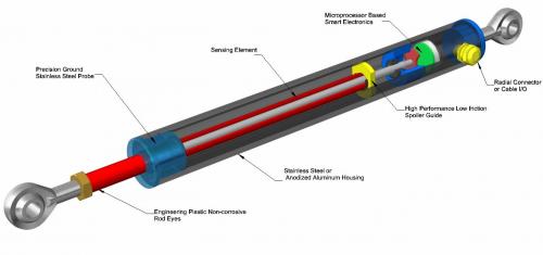
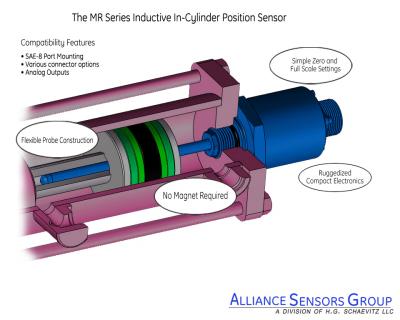
A sensor or transducer that measures a physical parameter, such as temperature, pressure, position, or fluid flow is connected to a signal conditioning circuit that converts the measured parameter value to an electrical output signal such as a voltage or current proportional to the measured physical parameter. If this electrical signal is a 4-20 mA DC output connected into a current loop, the hardware and electronics system which sends this current into the loop is called a transmitter. A transmitter may consist of a single device containing a sensing element and internal electronics, or it may utilize a sensor or transducer connected to separate signal conditioning electronics configured as a 4-20 mA current transmitter.

Field Wiring

The 4-20 mA current circulates in the loop. The distance between the sensor-transmitter combination and the process controller or readout can be several hundreds of feet or more. Field wiring conductors are used in the loop to connect the transmitter to the process monitoring or control hardware. It is important to see them as an element of the loop because they have some resistance and produce a voltage drop, just like any other element in the loop. If the sum of all the voltage drops is higher than the loop power supply compliance voltage, the current will not be proportional to the measured parameter and the system will produce unusable data.

The resistance of the field wiring conductors is normally given in Ohms per length, typically Ohms per 1000 feet, so the total resistance is the product of this value times the length of the wires divided by 1000. Note that the wire length includes the loop conductor going to the receiver and the loop conductor for the current return from the receiver, the sum of which is twice the individual conductor length. The total field wiring resistance is represented by the symbol Rw, as is shown in the diagram. The voltage drop due to the field wiring is given by Ohm’s law as:

Ohm's law equation   Where I is in Amperes; Rw is in Ohms; and Vw is in Volts.

Receiver or Process Controller 

After the loop current is generated, it must usually be further processed in the system.. For example, the current could be used as feedback to a valve controller to open, close, or modulate the valve in order to initiate or control a process. It is generally easier to perform control functions with a voltage rather than a current. The receiver is the the part of the loop circuit that converts the loop current into a voltage. In Figure 3, the receiver is a simple resistor that is in series with the loop, so from Ohm's Law, the voltage developed across it is directly proportional to the loop current, which is itself proportional to the measured physical parameter, the measurand.


Loop Load Resistor

The load resistor used in a 4-20 mA current loop is not an arbitrary value. For any specified compliance voltage, there is a maximum loop load resistance that will permit full current to be developed in the loop. Exceeding the maximum loop resistance, which must include the resistance of the field wiring, prevents the system from providing the full 20 mA output current in the loop. In the case of a typical current output sensor, whose loop load graph is shown in Figure 2 below, at 18 Volts input, the total loop load can be as high as 550 Ohms. At 24 Volts input, total loop load can be as high as 850 Ohms, and at the system's maximum input of 32 volts, the total loop load can be 1200 Ohms. 

Figure 2

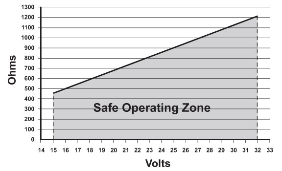
Figure 2 Loop load resistance vs. loop supply voltage for a typical current loop output sensor.


The Importance of Choosing the Right Loop Load Resistor

The choice of the loop load resistor usually depends on the input signal voltage the receiver system requires for good resolution. A 4-20 mA loop current will develop 2-10 VDC across a 500 Ohm load resistor (E = IR). If the receiver system will work satisfactorily with a lower input voltage, the 4-20 mA loop current will develop 1-5 VDC across a 250 Ohm load resistor, which is the most common loop load. Note that a loop load resistor is quite often already built into the receiver input terminal connections. Check the specifications of the receiving device to determine if there is a loop load resistor supplied at its input..  

It is very important that the loop load resistor wattage rating is sufficient to ensure that any heating caused by current flowing through the resistor won't change the resistor's value and thereby change the voltage developed across it. Recall that the wattage dissipated by the resistor is I² x R.  For a 500 Ohm load resistor, the power dissipated at 20 mA is 0.2 Watts. A good choice for the resistor's power rating is at least 2 Watts because such a load will not heat up very much. Even at full loop current there won’t be a voltage change across the load resistor due to heat from power dissipation instead of actual loop current changes. Note that wire-wound resistors usually have lower temperature coefficients than metallized resistors.


Types of Transmitters

There are several different varieties of current transmitters used for 4-20 mA current loops. In general, they conform to the following categories, delineated by the number of connections required for operation:

2-wire transmitters, which usually function as loop-powered current sinking devices.

-  3-wire transmitters, which are independently-powered loop current sourcing devices.

4-wire transmitters, which are normally independently-powered devices used when loop isolation is needed for noise or ground loop elimination, or for operation in hazardous locations (hazlocs).

-  Derivatives of 4-wire transmitters such as loop isolators or current loop repeaters. Often such devices are incorporated into a national-agency-approved safety barrier for intrinsically safe (IS) systems that can be safely operated in a code-specific hazardous location environment.


2-Wire Current Loop Powered Transmitters

2-wire loop-powered transmitters are electronic devices that can be connected in a current loop without having a separate or independent power source. They are designed to take their power from the current flowing in the loop. Typical loop-powered devices include sensors, transducers, transmitters, repeaters, isolators, meters, recorders, indicators, data loggers, monitors, and many other types of field instruments.

Loop-powered devices are important because for some systems it is difficult to supply separate power to all the devices and instruments in the loop. The device might be located in an enclosure where access might be difficult, or in a hazardous location (hazloc) where power cannot be allowed or must be limited.

Figure 3 shows a 2-wire loop-powered device connected to a current loop. It is considered a current sinking device in the loop circuit. The power to operate the device is supplied entirely by the unused current below 4 mA in the loop. 2-wire loop powered transmitters are popular, but are usually more costly than 3-wire transmitters.

Figure 3

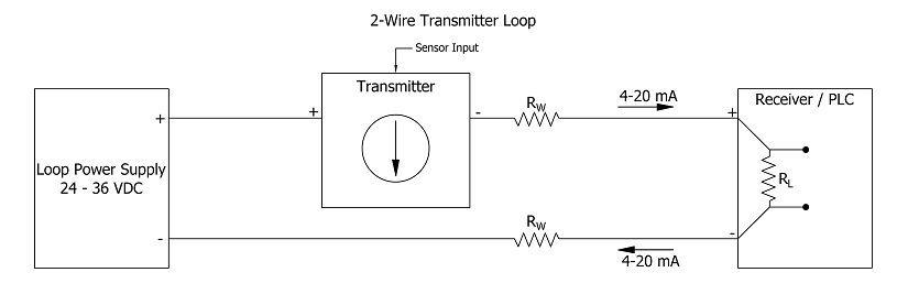
Figure 3 Typical 2-wire loop powered system

3-Wire Current Transmitters 

3-wire transmitters are different from loop-powered transmitters because their loop current is developed from a DC power supply that supplies more current than just the loop current. The entire transmitter operates off this supply, and may consume much more current than typical 2-wire loop powered devices. However, a 3-wire system is a sourcing element, so it supplies the current loop despite what it uses itself.  3-wire transmitters are often less costly than 2-wire. A typical 3-wire loop is shown in Figure 4 below. It is important to note that a 3-wire transmitter cannot be connected into a 2-wire loop powered system without significant loop circuit reconfiguration.

Figure 4

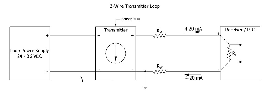
Figure 4 Typical current loop using a 3-wire transmitter 

Notice the high side of the power supply is not directly connected to the loop, but that the return side of the power supply is connected via a grounded point, so a 3-wire transmitter requires careful consideration of grounding issues to prevent potential ground loops. If an application using a 3-wire transmitter requires isolation in the loop, there are several paths to follow.

One way is to use a separate DC power supply for each 3-wire loop output device, so that there is no interaction with other current loops. Another way is to use a loop isolator module. These devices utilize various methods to achieve galvanic isolation, typically using transformers or optical couplers. They accept a 4-20 mA signal, function as a repeater or re-transmitter, and deliver a reconstituted 4-20 mA current loop signal that is fully isolated. A third way is to use a 4-wire transmitter which has isolation already built in.

4-Wire Current Transmitters

4-wire transmitters offer the current sourcing advantages of a 3-wire device, but also provide galvanic isolation for the current loop output. 4-wire devices are substantially more expensive than 3-wire devices. For this reason, they are generally used where the isolation is needed, or they are part of a combination device with an approved safety barrier for current loop operation in a specific hazardous location. A 4-wire transmitter block diagram is shown in Figure 5 below. A notable item is that the 4-wire device itself uses a separate DC power supply for operation, just like a 3-wire transmitter, and supplies loop current that way.

Figure 5

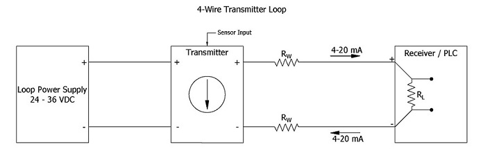
Figure 5 Typical current loop using a 4-wire transmitter

Review of 4-20 mA Data Transmission

The foregoing exposition has provided a brief description of the 4-20 mA current loop data transmission process. It is useful to conclude with a summary of the features and benefits of this process, as well as its limitations.   

Advantages

-  The 4-20 mA current loop is the dominant data transmission standard in many industries.

-  It is recognized as the simplest analog data transmission method to connect and configure.

It uses less wiring and connections than other methods, greatly reducing startup/setup costs.

 It is superior over long distances of field wiring, as current won't diminish, unlike voltage does.

It is relatively insensitive to most electrical noise and related EMI (electromagnetic interference).

-  It permits a local or a remote readout or monitoring device to be inserted in series with the loop.

-  It is self-diagnostic of faults in the measuring system because 4 mA is equal to a 0% system output, so a loop current substantially lower than 4 mA becomes an immediate indicator of a system fault.


Limitations

4-20 mA current loops can only transmit one specific sensor or process signal per loop.

Multiple loops are required for applications where there are many sensor or process outputs that must be transmitted. A lot of field wiring will be needed, which can lead to serious issues with ground loops if the independent current loops are not properly isolated from each other.

-  Isolation requirements become exponentially more complicated with a larger number of loops.

Those of us old enough to remember the “good old days” recall that grade school focused on learning the 3 R’s: reading, ‘riting, and ‘rithametic. In the world of sensors, there are also 3 R’s: Repeatability, Resolution, and Response. As important as these sensor parameters are, there is often confusion in the mind of users about exactly what they mean and in what ways they tend to interact with each other. This article attempts to explain these 3 R’s for position sensors and to dispel any confusion that exists.

DEFINITIONS

Repeatability is a measure of the variation between outputs of a sensor-based measuring system for repeated trials of an identical mechanical input in a constant environment. Common practice is to use at least 3 repeated inputs, but 5 or more identical inputs are considered to be an even better sample for determining this parameter. Repeatability is usually evaluated by applying an averaging process to the variations in output values observed for the multiple trials. It is typically specified as a percentage of Full Scale Output or Full Span Output (FSO), but sometimes it is specified in absolute terms such as parts per million or fractions of the mechanical units applicable to the actual sensor-based measurement.

A constraint on repeatability measurement is that the trial inputs have to be applied in the same way, usually from a lower value to higher value, to eliminate any effects from hysteresis. Hysteresis error is a measure of the difference in system output when the mechanical input is rising up to the desired input value from a lower value compared to an identical input coming down from a higher input value to the desired value. For most contactless position sensors, hysteresis error is smaller than repeatability error.

An example demonstrating repeatability can be seen in Figure 1, which shows a spring-loaded position sensor in a typical gaging stand being calibrated with a precision gage block of 0.5000 inch dimension. The sensor delivers an output of 0 to 10 Volts DC full scale for 0 to 1 inch of probe movement. The tip of the sensor is moved inward to allow the gage block to be inserted between the tip and a flat base, and then released to contact the block. In 5 trials, system outputs are: 5.0012, 5.0016, 5.0013, 5.0010, and 5.0015 Volts DC. The average value is slightly over 5.0013 Volts and the maximum variance is ±0.0003 Volts, which is equal to ±30 ppm of FSO, or 0.003% of FSO.

Resolution is a measure of the smallest change in the input to a sensor-based measuring system that will produce a measurable change in the electrical output from that system. While this may seem like a fairly simple concept, it is impacted by factors external to the sensor itself, the most significant of which is the signal-to-noise ratio of the system's analog output. Electrical noise present on the system's output can reduce the effective resolution of the system by masking any small changes in the sensor's output. For example, if the sensor's resolution specification is 0.25 mV, but the system output noise and ripple is 2 mVp-p, clearly sensor output changes smaller than 2 mV will not be discernable within that noise. Thus, the actual system resolution is only about 12% of what the sensor resolution specification offers.

Like repeatability, resolution is often specified as a percentage of Full Scale/Full Span Output (FSO) but may also be specified in absolute terms like fractions of the units of the actual sensor measurement, or, in digitally-augmented measurements, in bits, which is just a fractional measure expressed in powers of 2, as found in computers. Thus 10-bit resolution is 1 part in 1024 (210), 12-bit is 1 part in 4096 (212), etc.

Response denotes a sensor-based measuring system's performance under dynamic input conditions, that is, when the system's mechanical input is changing rapidly. It is particularly important to recognize that response is a measuring system parameter, not merely a sensor parameter or specification.

In practice, there are several ways to characterize response, typically based on whether the system is a first order or second order system. Traditional analog systems have used Bode plots to show frequency response and phase lag for repetitive inputs. For step function response, three times the system time constant is a typical measure of dynamic performance. In digital sampling systems, the update rate for a specified number of bits is one of the preferred measures of response. Regardless of the choice of how to specify response, the ultimate purpose is to understand how well the measuring system can respond to a changing input before the system's output becomes inaccurate, unusable, or unstable.

View Most Commonly Used LVITs Here! 

INTERACTIONS

From the foregoing definitions, it is easy to see that a system's repeatability could easily be affected by its resolution. If the measuring system's resolution is inadequate, it would likely be a significant limiting factor to excellent measurement system repeatability. In practice, sensor repeatability may be excellent, but measuring system repeatability cannot be any better than that permitted by the system's resolution.

While the interaction of repeatability with resolution in a measuring system is pretty easily understood, the interactions of resolution and response are not so straightforward. When the system's mechanical input is changing rapidly, the effects of resolution on system output are usually masked by the larger effects of decreased system output due to limitations imposed by the system's dynamic response. But if the mechanical input to a position measuring system changes slowly or intermittently, especially in a jerky way, then the effects of stiction (static friction) come into play.

Typically the effects of stiction in position measuring systems can be non-linear and are often not very repeatable, so determining or characterizing system resolution can be much more complicated, if even possible. And because the system resolution interacts with system repeatability, as was noted above, measurement errors can increase substantially, particularly if the system is providing position feedback for closed-loop control. Of course, any effects caused by stiction will also appear as non-linearity in the sensor's output. But because stiction effects are not very repeatable, digital linearization techniques to offset the non-linear effects will not be practical.

For this reason, efforts to reduce stiction are usually necessary to minimize any measurement errors caused by stiction in very slow-moving or intermittent-motion positioning systems. These efforts can involve applying techniques such as "dither", a low amplitude signal of high frequency that is input into the system to supplant stiction with much reduced dynamic friction, or by decreasing friction on the moving surfaces of the sensor by improving their surface finishes and by coating them with a lubricant.

 3Rs Figure


 Figure 1 Sensor Repeatability Testing Apparatus

What is LVIT Technology? LVITs, Linear Variable Inductive Transducers, have been around for more than 30 years, and are becoming very popular due to their relatively low cost and flexibility to be packaged in many different forms. LVITs are contactless position sensing devices that utilize eddy currents developed by an inductor in the surface of a conductive movable element to vary the resonant frequency of an L-C tank circuit. The most common form of an LVIT uses a small diameter inductive probe surrounded by a conductive tube called a “spoiler” that is mechanically coupled to the moving object. Typical LVITs have full ranges from fractions of an inch to 30 or more inches. Modern electronics using microprocessors and small component size makes outstanding performance possible, achieving linearity errors of less than ±0.1% and temperature coefficients of 50 ppm/ºF, along with either analog or digital outputs. The range of housing sizes for LVITs can be seen in Figure 1 and a cutaway view of an LVIT can be seen in Figure 2.


LVIT Linear Position Sensors

 
Figure 1


LVIT LR-27 Linear Position Sensor

 
Figure 2

LVITs are found in a wide variety of different applications that require position information or feedback. Typical LVIT applications include mobile hydraulics, subsea hardware, civil engineering testing, power generation and energy development, and factory automation.

In mobile hydraulics the LVIT is commonly used to measure hydraulic or pneumatic cylinder position. Usually the sensor has a pressure-sealed head and a probe long enough to insert into a gun-drilled hole in the cylinder’s ram. The ID of this hole in the ram then acts as the spoiler. The sensor head can either be port mounted or embedded into the end cap of the cylinder. A typical In-Cylinder LVIT installation is shown in Figure 3.


LVIT MR Series

 
Figure 3

This packaging fulfills many different applications in mobile hydraulics such as bulldozer shovel or snow plow positioning, boom positioning on hydraulic cranes and manlifts, and in a variety of agricultural vehicle accessory position feedback requirements

For Subsea Cylinder applications involving pumps, chokes, blowout preventers, and ROV-based actuators, the LVIT is designed to withstand the internal and/or external pressures of a PBOF (pressure balanced, oil filled) system. Other technologies commonly used to satisfy these applications require additional hardware like a ring magnet to operate, which adds cost to the machining of the cylinder ram and complexity to the installation. Typical subsea LVITs are shown in Figure 4.
 

LVIT MHP Series

 
Figure 4

Typical civil engineering applications include measuring bridge expansion and contraction due to seasonal heating and cooling, and related shifts in trunnions and roller support mechanisms. This problem of expansion and contraction is compounded with railway bridges and trackage, where the expansion of a mile-long section of rail could be as much as 4 feet over a change of temperature in some climates of 100 degrees F. This could lead to rail buckling, known in the industry as “sun kink,” and the derailment of a train. In this type of application, instead of having a bare probe protruding from the sensor head, the LVIT’s probe coil, spoiler, and electronics are packaged inside of a cylindrical housing for heavy duty protection, allowing the sensor to be exposed to its environment. The LVITs are connected to the pier and deck of the bridge to measure the relative position of the two, or directly to the rails to measure rail buckling. LVIT technology is extremely robust and so can withstand seasonal weather conditions such as heat, cold, rain, and snow. An example of an installation of heavy duty LVITs on a bridge is shown in Figure 5.


LVIT Linear Position Sensor on Bridge

 
Figure 5

LVITs are used in many factory automation applications, including packaging and material handling equipment, die platen position in plastic molding machines, roller position and web tension controls in paper mills or converting facilities, and robotic spray painting systems. Being contactless, the basic measurement mechanism of an LVIT does not wear out over time. LVITs also do not have the higher installed cost associated with other contactless technologies.

LVITs are being utilized in specific areas of the energy sector. In power generation applications, LVITs are used for valve position feedback, feedwater pump displacement, or generator shell movement. In oil fields, LVITs are used in hydraulic-operated pumps that replace Lufkin-style pump jacks, and to measure the poppet position inside check valves.

Alliance Sensors Group’s LVIT product line is offered with ASG’s proprietary SenSet™ field programmable scaling, which allows a user to adjust for mechanical variations after installation in the application simply by pushing a button or grounding a connection. This SenSet™ feature reduces setup time and cost of ownership. For example, SenSet™ allows a rising stem valve that opens 9.5 inches to be coupled to a 10-inch range LVIT and get full scale output over the 9.5 inches by scaling the sensor’s output after it has been installed.

From the foregoing exposition, it is apparent that LVITs represent a valuable and cost-effective position measuring technology for a broad range of applications.


Comparative Characteristics of Various Linear Position / Displacement Sensor Technologies


https://alliancesensors.com/sites/default/files/images/PDF/pos_tech_comp_v1.pdf