LVDT Position Sensor FAQ

How they work and how to operate them with an ASG S2A LVDT signal conditioner

By: Ed Herceg  Chief Technology Officer 

GE Position Sensors for Power Generation Turbines

How they work and how to operate them with an ASG S2A LVDT signal conditioner


LVDTs (Linear Variable Differential Transformers) are very commonly used as position sensors in power plants throughout the world.  Working from AC voltages and frequencies not available from power lines, LVDTs require a signal conditioner to provide the necessary operating power. Alliance Sensors Group's model S2A module, designed specifically to be used in power gen applications, is considered by many power gen users be the most advanced and easy-to-use single channel LVDT signal conditioner on the market today. It can operate practically any LVDT or half-bridge (LVRT) position sensor currently in use. 


However, users and systems integrators can be confused by unusual LVDT configurations, particularly in regard to the General Electric 185A1328 and 311A5178 series of LVDTs typically used with their gas turbines.  Furthermore, for many years, GE has been using a contactless position sensor known as an inductive half-bridge for measuring the position of the operating shafts of steam turbine control valves.  These sensors, often called VRTs or LVRTs, are used to provide position feedback from modulating throttle and governor valves, as well as to give open or closed condition feedback from bypass, stop, and interceptor valves.  They are also used to monitor valve position on some turbine feedwater pumps.  Some typical GE half-bridge part numbers include the 119C9638, 119C9639, and 196C8768 series.   Again, there is some confusion among many systems integrators about how to connect these GE half-bridge sensors to an LVDT signal conditioner and how to calibrate them. This paper should help dispel any confusion about operating an S2A with a GE gas turbine LVDT or steam turbine half-bridge sensor.


Operating GE Gas Turbine LVDTs with an ASG S2A LVDT Signal Conditioner


The first section of this paper shows how these GE LVDTs differ from conventional LVDTs and how to operate them with an S2A LVDT signal conditioner module.  To understand the differences between GE Gas Turbine LVDTs and conventional LVDTs, it is important to review the characteristics of an ordinary LVDT.  Regardless of the method of construction actually used to make a conventional LVDT, it has a primary winding and two identical secondary windings that are usually connected in series opposition, with a movable permeable core to couple the primary to the secondaries, as shown in Figure 1 below.

The electrical output of a typical LVDT as a function of its core's position is shown in Figure 2 below.  Note that the plot of its AC output amplitude versus position shows the classical "V" shape commonly associated with an LVDT, with a minimum value called null at the center of its range of motion, and an increased output amplitude for core positions on either side of null. More important is the fact that the phase relationship of the differential AC output to the primary input voltage shifts abruptly by 180° as the core moves through null. It is this 180° phase shift that permits a user to know on which side of null the core is positioned.  The voltages and frequency shown are typical of those found in the operation of a conventional LVDT. It is important to note that the actual excitation voltage utilized makes very little difference to an LVDT's performance. Only the excitation frequency is important for proper operation.

The configuration of the LVDTs used by GE for various position sensing functions on their gas turbines is shown in Figure 3 below.  The most obvious difference is the tap on the primary, but otherwise it does not seem to vary much from the view of a conventional LVDT. However, its electrical operation is really substantially different.  Although it is tempting to view the primary tap as a center tap, it is not a center tap at all. Most often it is a 30% tap, but on a few models it is a 25% tap. The voltages shown are typical of those used by GE, but, as noted above, the sensor is a differential transformer and will function with whatever AC voltage is applied to operate it. For the sake of clarity, typical GE I/O values are used for the explanation of how this variety of LVDT works.


This LVDT hookup is generally known as a "Buck-Boost" configuration.  As can be seen in Figure 3, the voltage at the tap is 30% of the excitation voltage that is being applied to the LVDTs primary, and is in phase with the primary voltage. The way the windings are connected, this 30% voltage, etap, is being added to the differential secondary voltage, which consists of e1, which is in phase with the primary voltage, to which has been added e2, which is 180° out of phase with the primary voltage. The turns ratio of these GE LVDTs is usually about 5:1, so, with a 7.07 V ACrms input, the full scale output of the secondaries, without the effect of the 30% tap, would be about 1.4 V ACrms, either in phase with the primary excitation or 180° out of phase with it. However, the 30% tap inserts an additional 2.1 V ACrms that is in phase with the primary excitation to be added to the voltages already in the secondaries. The result is plotted in Figure 4, which shows that the total AC output from the series connection of the two secondaries and the 30% tap is a voltage between 0.7 to 3.5 V ACrms, with no 180° phase shift as the LVDT's core moves from one end of its range of motion through null to the other end of its range.

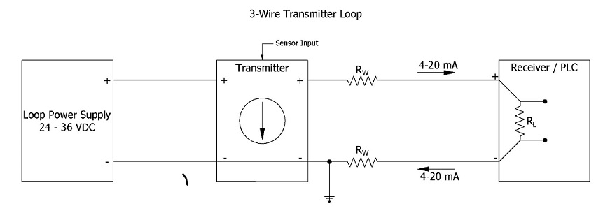
The electronics used by GE in their controllers requires this unusual AC output, but almost all these "Buck-Boost" LVDTs can be successfully operated with an ASG S2A signal conditioner module by using the appropriate connection configuration. The first thing to do is to ignore any connection to the primary tap. Instead, connect the LVDT in a 3-wire configuration, as shown in the S2A instruction manual. In this configuration, the high end of the primary is connected to J1-1 (or J1-2, if the output directional sense is reversed), the common connection of the primary and the series-connected secondaries is connected to J1-3, and the secondaries' high output is connected to J1-4. It is also necessary to move jumper J10 to its alternate position and to shift jumper J7 over to its high output position to increase the excitation to the LVDT's primary. After this 3-wire connection for a "Buck-Boost" LVDT has been completed, the S2A can be operated and the LVDT be calibrated in the normal manner shown in the S2A module's manual.

Operating GE Steam Turbine Half-bridge (LVRT) Sensors with an S2A Signal Conditioner


First it is necessary to understand how GE half-bridge sensors function to see how to use them with an S2A signal conditioner.  Figure 5 shows the schematic of a typical GE half-bridge sensor. Note that pins D and E play no role in the operation of the sensor, but are merely part of an "interrupt jumper" system which is used to notify the turbine control system that the connector has been removed.  As shown in the schematic, the sensor consists of two identically-wound inductor coils connected in series encircling a movable permeable core long enough to overlap a portion of each coil. An AC voltage ein is applied to pins A and C.  If the core is located symmetrically between the coils, each coil will have the same impedance and, assuming the output has no load, voltage eout between pins B and C will be 1/2 of ein.

If the core is moved to include more of the coil connected between pins A and B, the inductance, and therefore the impedance, of that winding will increase, while the inductance, and hence the impedance, of the coil connected between pins B and C will decrease.  The result will be a drop in the voltage eout.  If the core were moved in the other direction, the reverse action would happen and eout would increase. 

Thus, the half-bridge acts as an AC voltage divider. Over a limited range of motion, and excited at an appropriate input frequency, this operation can be reasonably linear if the change in impedance of each winding is largely due to its inductance rather than to its DC resistance, as shown in Figure 6 below.

The shaded symmetrical areas represent the different AC output levels developed by different sensors. Several things stand out in Figure 6. First is that the output at mid-range is not zero as with an LVDT, but is half of the AC excitation. Second, there is not a 180° phase shift at "null" as with an LVDT. Both features specifically facilitate interfacing these sensors with GE's Mark 2 - 6 turbine control systems.


There are two other very important points of note in the operation of half-bridge sensors, both of which concern the excitation of the sensors. First, the magnitude of the AC excitation voltage has no bearing at all on the functioning of these sensors. The choice of 7.07 Vrms (20 Vp-p) by GE is merely dependent on the requirements of their control system. Second, the excitation frequency is chosen to make sure the impedance of the two windings is dominated by their inductive reactance at the chosen frequency, so that the DC resistance of the windings has a fairly small overall effect on the winding impedances.


When looking at Figure 6, it is easy to understand why it can be unduly difficult to set up and calibrate these GE half-bridge position sensors in the field.  The primary reason is that a half-bridge sensor does not have a uniquely identifiable point in its range of motion like an LVDT's null point. Fortunately, ASG's S2A LVDT signal conditioner was designed not merely to work with inductive half-bridges, but to make their operation emulate that of an LVDT. Thus, anyone familiar with the techniques for calibrating an LVDT position sensor installed in a valve position feedback system using an S2A module will be able to utilize those very same techniques to calibrate a GE half-bridge sensor connected to an S2A module. 


Figure 7 below shows that a GE inductive half-bridge connected to an S2A signal conditioner displays exactly the same type of AC output as would be developed if the S2A were connected to an LVDT. When using an S2A with a half-bridge sensor, the front panel LEDs function in the same way during calibration as if it were an LVDT, as does the Null Output voltage available at J4-1 and J4-2.  While this app note has focused on the GE half-bridges used in power plants, these same considerations apply to operating any inductive half-bridge sensor with an S2A or any of its derivative LVDT signal conditioners.


The connection diagram for hooking up GE half-bridges to an S2A signal conditioner module is shown above. Hook up the GE half-bridge connector's pins to the numbers on the black plug, J1, as follows: Pin A goes to J1-1, pin B goes to J1-4, and pin C goes to J1-2.  Pins E and F are not connected to the S2A at all. Also, move jumpers J7 and J10 over to their alternate positions. If the directional sense of the S2A's analog output is reversed from the desired output, either interchange the connections to J1-1 and J1-2, or flip the INVERT switch, DS2-3, inside of the S2A.


50/60 Hz GE Half-bridge Sensors used with ASG S2A Signal Conditioners in Steam Power Plants


This paper was based on the most common GE half-bridge sensors likely to be found in power plants today, all of which operate at 3 kHz.  However, early on, GE used some half-bridge sensors that were operated with 24 Volts AC at 50/60 Hz and some even used 115 Volts AC, 50/60 Hz. Both systems integrators and power gen utilities should be aware of the risks of continuing to use a more than half-century old design of 50/60 Hz-operated GE half-bridges instead of the newer 3 kHz-operated sensors.


These 50/60 Hz units do not contain much ferromagnetic material beyond their core so their windings utilize many turns of fine wire to achieve the needed inductance.  As a result, their winding impedance has a large resistive component, so that much of the AC input power gets dissipated in the resistance of the windings, leading these sensors to get quite hot internally during normal operation.


Because of the effects of thermal expansion and contraction on the winding insulation, these 50/60 Hz units have a history of developing intra-winding shorts, but which do not immediately produce significant output changes because there are so many turns of wire on each winding.  Furthermore, sensor output linearity is also poor to begin with, typically ± 2% at FSO, and ± 5% at 110% of FSO, which often initially masks the effects of any such internal shorts. But over a period of time, the internal winding shorts can and often do increase, causing a net calibration shift that could result in a significant sensor output error.


Despite these issues, several integrators have had success using these old 50/60 Hz GE half-bridge sensors with an ASG S2A LVDT signal conditioner by operating them with the S2A's 1 kHz excitation frequency. In fact, some old sensors had such a low winding impedance at 1 kHz that it was necessary to operate them at 3 kHz. Typically, those integrators have utilized old stock of unused spares or ordered new units built to the old design, mostly because their utility customers are reluctant to change sensors over to newer, more reliable products, particularly in nuclear power plants, because of issues with certifications, testing, and related documentation.  Even so, it is important to bear in mind that these 50/60 Hz sensors utilize a genuinely obsolete design, and that contactless inductive position sensing technology and sensor reliability have improved substantially in the intervening half-century or more.

To download a PDF of this FAQ, please click here.

Could you please explain the 4 to 20 mA Current Loops

4 to 20 mA Current Loops Made Easy

Understanding current loop output sensors

For analog sensor data transmission, a 4-20 mA current loop is a very common method to convey the sensor data acquired. Sensors or transducers are usually designed to measure a range of values of the measured parameter, which is known as the measurand. The measurand value must be converted to current within the measuring device in such a way that the current in the loop will be proportional to the measurand value. The range of the loop current, 4 mA to 20 mA, is called the span of the transmitter. The transmitter is typically configured so that one end point of the measurement value will correspond to 4 mA and the other end point value measured will correspond to 20 mA.

The 4-20 mA current loop has become the standard for signal transmission and electronic control in most analog control systems. A 4-20 mA current loop circuit is shown in Figure 1.  In a current loop, the current is drawn from a DC loop power supply, then flows through the transmitter using field wiring connected to a loop load resistor in the receiver or controller, and then back to the loop supply, with all elements being connected in a series circuit. All current-loop-based measuring systems use at least these four elements.

Figure 1

Figure 1.Typical 4-20 mA current loop


Advantages of a Current Loop

An obvious question arises: Why use a 4-20 mA current loop to transmit the analog data from a sensor? The answer is that a 4-20 mA current loop offers several benefits for such sensor data transmission:

-  A major reason is that the loop current does not vary with long field wiring, as long as the voltage developed in the loop, called the Compliance Voltage, can sustain the maximum loop current.

-  Another benefit is that the current loop has a low impedance and is not particularly susceptible to noise or EMI at large.

-  A third advantage is the live-zero feature of the loop (the 4 mA low limit), which makes the loop self-diagnostic if there is a break or bad connection in the loop or a loop power supply failure.

-  A current loop permits other current operated devices such as a remote readout or a recorder to be put in series with the loop, within the constraints permitted by the loop's Compliance Voltage.

-  The low level of maximum loop current (20 mA) allows the use of relatively simple safety barriers to limit loop current to an Intrinsically Safe level that prevents ignition in a Hazardous Location.


Loop Power Supply and Compliance Voltage

When current is transmitted in the loop, there are voltage drops due to the field wiring conductors and any connected devices. However, these voltage drops do not affect the current in the loop as long as the total loop voltage is sufficient to maintain the maximum loop current. The element responsible for maintaining a stable current in the loop (as shown in Figure 1) is the loop DC power supply. The range of voltage over which the loop will function is called its Compliance Voltage.  Common values for 4-20 mA loop supplies are 24VDC or 36VDC. The voltage chosen by a designer depends on the number of elements connected in series with the loop, because the loop power supply voltage must always be higher than the sum of all the voltage drops in the circuit, including the field wiring voltage drop. The sum of all these voltage drops is known as the loop's minimum compliance voltage.

There are certain requirements that the compliance voltage must be able to fulfill, the two most important of which are: 

-  The power supply voltage must be able to power all the devices in the loop, including the field wiring voltage drop, when the current is at its maximum value, normally 20 mA.

-  The loop power supply maximum voltage output must be equal to or lower than the maximum voltage rating of any device in the loop.

Transmitter

A sensor or transducer that measures a physical parameter, such as temperature, pressure, position, or fluid flow is connected to a signal conditioning circuit that converts the measured parameter value to an electrical output signal such as a voltage or current proportional to the measured physical parameter. If this electrical signal is a 4-20 mA DC output connected into a current loop, the hardware and electronics system which sends this current into the loop is called a transmitter. A transmitter may consist of a single device containing a sensing element and internal electronics, or it may utilize a sensor or transducer connected to separate signal conditioning electronics configured as a 4-20 mA current transmitter.

Field Wiring

The 4-20 mA current circulates in the loop. The distance between the sensor-transmitter combination and the process controller or readout can be several hundreds of feet or more. Field wiring conductors are used in the loop to connect the transmitter to the process monitoring or control hardware. It is important to see them as an element of the loop because they have some resistance and produce a voltage drop, just like any other element in the loop. If the sum of all the voltage drops is higher than the loop power supply compliance voltage, the current will not be proportional to the measured parameter and the system will produce unusable data.

The resistance of the field wiring conductors is normally given in Ohms per length, typically Ohms per 1000 feet, so the total resistance is the product of this value times the length of the wires divided by 1000. Note that the wire length includes the loop conductor going out and the loop conductor for the current return, which is twice the individual conductor length. The total wiring resistance is represented by the symbol Rw, as is shown in the diagram. The voltage drop due to the field wiring is given by Ohm’s law:

Ohm's law equation   Where I is in Amperes; Rw is in Ohms; and Vw is in Volts.

Receiver or Process Controller 

After the loop current is generated, it must usually be further processed in the system.. For example, the current could be used as feedback to a valve controller to open, close, or modulate the valve in order to initiate or control a process. It is easier to perform control functions with a voltage rather than a current. The receiver is the the part of the loop circuit that converts the loop current into a voltage. In Figure 3, the receiver is a simple resistor that is in series with the loop, so from Ohm's Law, the voltage developed across it is directly proportional to the measured physical parameter, the measurand.


Loop Load Resistor

The load resistor used in a 4-20 mA current loop is not an arbitrary value. For any specified compliance voltage, there is a maximum loop load resistance that will permit full current to be developed in the loop. Exceeding the maximum loop resistance, which must include the resistance of the field wiring, prevents the system from providing the full 20 mA output current in the loop. In the case of a typical current output sensor, whose loop load graph is shown in Figure 2 below, at 18 Volts input, the total loop load can be as high as 550 Ohms. At 24 Volts input, total loop load can be as high as 850 Ohms, and at the system's maximum input of 32 volts, the total loop load can be 1200 Ohms. 

Figure 2

Figure 2 Loop load resistance vs. loop supply voltage for a typical current loop output sensor.


The Importance of Choosing the Right Loop Load Resistor

The choice of the loop load resistor usually depends on the input signal voltage the receiver system requires for good resolution. A 4-20 mA loop current will develop 2-10 VDC across a 500 Ohm load resistor (E = IR). If the receiver system will work satisfactorily with a lower input voltage, the 4-20 mA loop current will develop 1-5 VDC across a 250 Ohm load resistor, which is the most common loop load. Note that a loop load resistor is quite often already built into the receiver input terminal connections. Check the specifications of the receiving device to determine if there is a loop load resistor supplied at its input..  

It is very important that the loop load resistor wattage rating is sufficient to ensure that any heating caused by current flowing through the resistor won't change the resistor's value and thereby change the voltage developed across it. Recall that the wattage dissipated by the resistor is I² x R.  For a 500 Ohm load resistor, the power dissipated at 20 mA is 0.2 Watts. A good choice for the resistor's power rating is at least 2 Watts because such a load will not heat up very much. Even at full loop current there won’t be a voltage change across the load resistor due to heat from power dissipation instead of actual loop current changes. Wire-wound resistors usually have lower temperature coefficients than metallized resistors.

Types of Transmitters

There are several different varieties of current transmitters used for 4-20 mA current loops. In general, they conform to the following categories, delineated by the number of connections required for operation:

- 2-wire transmitters, which usually function as loop-powered current sinking devices.

- 3-wire transmitters, which are independently-powered loop current sourcing devices.

- 4-wire transmitters, which are normally independently-powered devices used when loop isolation is needed for noise or ground loop elimination, or for operation in hazardous locations (hazlocs).

- Derivatives of 4-wire transmitters such as loop isolators or current loop repeaters. Often such devices are incorporated into a national-agency-approved safety barrier for intrinsically safe (IS) systems that can be safely operated in a code-specific hazardous location environment.


2-Wire Current Loop Powered Transmitters

2-wire loop-powered transmitters are electronic devices that can be connected in a current loop without having a separate or independent power source. They are designed to take their power from the current flowing in the loop. Typical loop-powered devices include sensors, transducers, transmitters, repeaters, isolators, meters, recorders, indicators, data loggers, monitors, and many other types of field instruments.

Loop-powered devices are important because for some systems it is difficult to supply separate power to all the devices and instruments in the loop. The device might be located in an enclosure where access might be difficult, or in a hazardous location (hazloc) where power cannot be allowed or must be limited.

Figure 3 shows a 2-wire loop-powered device connected to a current loop. It is considered a current sinking device in the loop circuit. The power to drive the device is supplied entirely by the unused current below 4 mA in the loop. 2-wire loop powered transmitters are popular, but usually more costly than 3-wire.

Figure 3

Figure 3 Typical 2-wire loop powered system

3-Wire Current Transmitters 

3-wire transmitters are different from loop-powered transmitters because their loop current is developed from a DC power supply that supplies more current than just the loop current. The entire transmitter operates off this supply, and may consume much more current than typical 2-wire loop powered devices. However, a 3-wire system is a sourcing element, so it supplies the current loop despite what it uses itself.  3-wire transmitters are often less costly than 2-wire. A typical 3-wire loop is shown in Figure 4 below. It is important to note that a 3-wire transmitter should never be connected to any 2-wire loop powered system.

Figure 4

Figure 4 Typical current loop using a 3-wire transmitter 


Notice the high side of the power supply is not directly connected to the loop, but that the return side of the power supply is connected via a grounded point, so a 3-wire transmitter requires careful consideration of grounding issues to prevent potential ground loops. If an application using a 3-wire transmitter requires isolation in the loop, there are several paths to follow.

One way is to use a separate DC power supply for each 3-wire loop output device, so that there is no interaction with other current loops. Another way is to use a loop isolator module. These devices utilize various methods to achieve galvanic isolation, typically using transformers or optical couplers. They accept a 4-20 mA signal, function as a repeater or re-transmitter, and deliver a reconstituted 4-20 mA current loop signal that is fully isolated. A third way is to use a 4-wire transmitter which has isolation already built in.

4-Wire Current Transmitters

4-wire transmitters offer the current sourcing advantages of a 3-wire device, but also provide galvanic isolation for the current loop output. 4-wire devices are substantially more expensive than 3-wire devices. For this reason, they are generally used where the isolation is needed, or they are part of a combination device with an approved safety barrier for current loop operation in a specific hazardous location. A 4-wire transmitter block diagram is shown in Figure 5 below. A notable item is that the 4-wire device itself uses a separate DC power supply for operation, just like a 3-wire transmitter, and supplies loop current that way.

Figure 5

Figure 5 Typical current loop using a 4-wire transmitter

Review of 4-20 mA Data Transmission

The foregoing exposition has provided a succinct description of the 4-20 mA data transmission process. It is useful to conclude with a summary of the features and benefits of this process, as well as its limitations.   

Advantages

-  The 4-20 mA current loop is the dominant data transmission standard in many industries.

-  It is recognized as the simplest analog data transmission method to connect and configure.

-  It uses less wiring and connections than other methods, greatly reducing startup/setup costs.

-  It is superior over long distances of field wiring, as current won't diminish, unlike voltage does.

-  It is relatively insensitive to most electrical noise and related EMI (electromagnetic interference).

-  It permits a local or a remote readout or monitoring device to be inserted in series with the loop.

-  It is self-diagnostic of faults in the measuring system because 4 mA is equal to 0% system output, so any loop current substantially lower than 4 mA becomes an immediate indicator of loop fault.


Limitations

-  4-20 mA current loops can only transmit one specific sensor or process signal per loop.

-   Multiple loops are required for applications where there are many sensor or process outputs that must be transmitted. A lot of field wiring will be needed, which can lead to serious issues  with ground loops if the independent current loops are not properly isolated from each other.

-  Isolation requirements become exponentially more complicated with a larger number of loops.


Can you please explain the 4 to 20 mA current loop?


Understanding current loop output sensors

For analog sensor data transmission, a 4-20 mA current loop is a very common method to convey the sensor data acquired. Sensors or transducers are usually designed to measure a range of values of the measured parameter, which is known as the measurand. The measurand value must be converted to current within the measuring device in such a way that the current in the loop will be proportional to the measurand value. The range of the loop current, 4 mA to 20 mA, is called the span of the transmitter. The transmitter is typically configured so that one end point of the measurement value will correspond to 4 mA and the other end point value measured will correspond to 20 mA.

The 4-20 mA current loop has become the standard for signal transmission and electronic control in most analog control systems. A 4-20mA current loop circuit is shown in Figure 1.  In a current loop, the current is drawn from a DC loop power supply, then flows through the transmitter using field wiring connected to a loop load resistor in the receiver or controller, and then back to the loop supply, with all elements being connected in a series circuit. All current-loop-based measuring systems use at least these four elements.

Figure 1

Figure 1.Typical 4-20 mA current loop


Advantages of a Current Loop

An obvious question arises: Why use a 4-20 mA current loop to transmit the analog data from a sensor? The answer is that a 4-20 mA current loop offers several benefits for such sensor data transmission:

-  A major reason is that the loop current does not vary with long field wiring, as long as the voltage developed in the loop, called the Compliance Voltage, can sustain the maximum loop current.

-  Another benefit is that the current loop has a low impedance and is not particularly susceptible to noise or EMI at large.

A third advantage is the live-zero feature of the loop (the 4 mA low limit), which makes the loop self-diagnostic if there is a break or bad connection in the loop or a loop power supply failure.

-  A current loop permits other current operated devices such as a remote readout or a recorder to be put in series with the loop, within the constraints permitted by the loop's Compliance Voltage.

-  The low level of maximum loop current (20 mA) allows the use of relatively simple safety barriers to limit loop current to an Intrinsically Safe level that prevents ignition in a Hazardous Location.


Loop Power Supply and Compliance Voltage

When current is transmitted in the loop, there are voltage drops due to the field wiring conductors and any connected devices. However, these voltage drops do not affect the current in the loop as long as the total loop voltage is sufficient to maintain the maximum loop current. The element responsible for maintaining a stable current in the loop (as shown in Figure 1) is the loop DC power supply. The range of voltage over which the loop will function is called its Compliance Voltage.  Common values for 4-20 mA loop supplies are 24VDC or 36VDC. The voltage chosen by a designer depends on the number of elements connected in series with the loop, because the loop power supply voltage must always be higher than the sum of all the voltage drops in the circuit, including the field wiring voltage drop. The sum of all these voltage drops is known as the loop's minimum compliance voltage. There are certain requirements that the compliance voltage must be able to fulfill, the two most important of which are: 

The loop power supply voltage must be able to power all the devices in the loop, including the field wiring's voltage drop, when the current is at its maximum value, normally 20 mA.

-  The loop power supply maximum voltage output must be equal to or lower than the maximum voltage rating of any device in the loop.

Transmitter

A sensor or transducer that measures a physical parameter, such as temperature, pressure, position, or fluid flow is connected to a signal conditioning circuit that converts the measured parameter value to an electrical output signal such as a voltage or current proportional to the measured physical parameter. If this electrical signal is a 4-20 mA DC output connected into a current loop, the hardware and electronics system which sends this current into the loop is called a transmitter. A transmitter may consist of a single device containing a sensing element and internal electronics, or it may utilize a sensor or transducer connected to separate signal conditioning electronics configured as a 4-20 mA current transmitter.

Field Wiring

The 4-20 mA current circulates in the loop. The distance between the sensor-transmitter combination and the process controller or readout can be several hundreds of feet or more. Field wiring conductors are used in the loop to connect the transmitter to the process monitoring or control hardware. It is important to see them as an element of the loop because they have some resistance and produce a voltage drop, just like any other element in the loop. If the sum of all the voltage drops is higher than the loop power supply compliance voltage, the current will not be proportional to the measured parameter and the system will produce unusable data.

The resistance of the field wiring conductors is normally given in Ohms per length, typically Ohms per 1000 feet, so the total resistance is the product of this value times the length of the wires divided by 1000. Note that the wire length includes the loop conductor going to the receiver and the loop conductor for the current return from the receiver, the sum of which is twice the individual conductor length. The total field wiring resistance is represented by the symbol Rw, as is shown in the diagram. The voltage drop due to the field wiring is given by Ohm’s law as:

Ohm's law equation   Where I is in Amperes; Rw is in Ohms; and Vw is in Volts.

Receiver or Process Controller  

After the loop current is generated, it must usually be further processed in the system.. For example, the current could be used as feedback to a valve controller to open, close, or modulate the valve in order to initiate or control a process. It is generally easier to perform control functions with a voltage rather than a current. The receiver is the the part of the loop circuit that converts the loop current into a voltage. In Figure 3, the receiver is a simple resistor that is in series with the loop, so from Ohm's Law, the voltage developed across it is directly proportional to the loop current, which is itself proportional to the measured physical parameter, the measurand.


Loop Load Resistor

The load resistor used in a 4-20 mA current loop is not an arbitrary value. For any specified compliance voltage, there is a maximum loop load resistance that will permit full current to be developed in the loop. Exceeding the maximum loop resistance, which must include the resistance of the field wiring, prevents the system from providing the full 20 mA output current in the loop. In the case of a typical current output sensor, whose loop load graph is shown in Figure 2 below, at 18 Volts input, the total loop load can be as high as 550 Ohms. At 24 Volts input, total loop load can be as high as 850 Ohms, and at the system's maximum input of 32 volts, the total loop load can be 1200 Ohms. 

Figure 2

Figure 2 Loop load resistance vs. loop supply voltage for a typical current loop output sensor.


The Importance of Choosing the Right Loop Load Resistor

The choice of the loop load resistor usually depends on the input signal voltage the receiver system requires for good resolution. A 4-20 mA loop current will develop 2-10 VDC across a 500 Ohm load resistor (E = IR). If the receiver system will work satisfactorily with a lower input voltage, the 4-20 mA loop current will develop 1-5 VDC across a 250 Ohm load resistor, which is the most common loop load. Note that a loop load resistor is quite often already built into the receiver input terminal connections. Check the specifications of the receiving device to determine if there is a loop load resistor supplied at its input..  

It is very important that the loop load resistor wattage rating is sufficient to ensure that any heating caused by current flowing through the resistor won't change the resistor's value and thereby change the voltage developed across it. Recall that the wattage dissipated by the resistor is I² x R.  For a 500 Ohm load resistor, the power dissipated at 20 mA is 0.2 Watts. A good choice for the resistor's power rating is at least 2 Watts because such a load will not heat up very much. Even at full loop current there won’t be a voltage change across the load resistor due to heat from power dissipation instead of actual loop current changes. Note that wire-wound resistors usually have lower temperature coefficients than metallized resistors.


Types of Transmitters


There are several different varieties of current transmitters used for 4-20 mA current loops. In general, they conform to the following categories, delineated by the number of connections required for operation:

2-wire transmitters, which usually function as loop-powered current sinking devices.

-  3-wire transmitters, which are independently-powered loop current sourcing devices.

-  4-wire transmitters, which are normally independently-powered devices used when loop isolation is needed for noise or ground loop elimination, or for operation in hazardous locations (hazlocs).

-  Derivatives of 4-wire transmitters such as loop isolators or current loop repeaters. Often such devices are incorporated into a national-agency-approved safety barrier for intrinsically safe (IS) systems that can be safely operated in a code-specific hazardous location environment.


2-Wire Current Loop Powered Transmitters


2-wire loop-powered transmitters are electronic devices that can be connected in a current loop without having a separate or independent power source. They are designed to take their power from the current flowing in the loop. Typical loop-powered devices include sensors, transducers, transmitters, repeaters, isolators, meters, recorders, indicators, data loggers, monitors, and many other types of field instruments.

Loop-powered devices are important because for some systems it is difficult to supply separate power to all the devices and instruments in the loop. The device might be located in an enclosure where access might be difficult, or in a hazardous location (hazloc) where power cannot be allowed or must be limited.

Figure 3 shows a 2-wire loop-powered device connected to a current loop. It is considered a current sinking device in the loop circuit. The power to operate the device is supplied entirely by the unused current below 4 mA in the loop. 2-wire loop powered transmitters are popular, but are usually more costly than 3-wire transmitters.

Figure 3

Figure 3 Typical 2-wire loop powered system


3-Wire Current Transmitters 

3-wire transmitters are different from loop-powered transmitters because their loop current is developed from a DC power supply that supplies more current than just the loop current. The entire transmitter operates off this supply, and may consume much more current than typical 2-wire loop powered devices. However, a 3-wire system is a sourcing element, so it supplies the current loop despite what it uses itself.  3-wire transmitters are often less costly than 2-wire. A typical 3-wire loop is shown in Figure 4 below. It is important to note that a 3-wire transmitter cannot be connected into a 2-wire loop powered system without significant loop circuit reconfiguration.

Figure 4

Figure 4 Typical current loop using a 3-wire transmitter

Notice the high side of the power supply is not directly connected to the loop, but that the return side of the power supply is connected via a grounded point, so a 3-wire transmitter requires careful consideration of grounding issues to prevent potential ground loops. If an application using a 3-wire transmitter requires isolation in the loop, there are several paths to follow.

One way is to use a separate DC power supply for each 3-wire loop output device, so that there is no interaction with other current loops. Another way is to use a loop isolator module. These devices utilize various methods to achieve galvanic isolation, typically using transformers or optical couplers. They accept a 4-20 mA signal, function as a repeater or re-transmitter, and deliver a reconstituted 4-20 mA current loop signal that is fully isolated. A third way is to use a 4-wire transmitter which has isolation already built in.

4-Wire Current Transmitters

4-wire transmitters offer the current sourcing advantages of a 3-wire device, but also provide galvanic isolation for the current loop output. 4-wire devices are substantially more expensive than 3-wire devices. For this reason, they are generally used where the isolation is needed, or they are part of a combination device with an approved safety barrier for current loop operation in a specific hazardous location. A 4-wire transmitter block diagram is shown in Figure 5 below. A notable item is that the 4-wire device itself uses a separate DC power supply for operation, just like a 3-wire transmitter, and supplies loop current that way.

Figure 5

Figure 5 Typical current loop using a 4-wire transmitter


Review of 4-20 mA Data Transmission

The foregoing exposition has provided a brief description of the 4-20 mA current loop data transmission process. It is useful to conclude with a summary of the features and benefits of this process, as well as its limitations.     

Advantages

-  The 4-20 mA current loop is the dominant data transmission standard in many industries.

-  It is recognized as the simplest analog data transmission method to connect and configure.

-  It uses less wiring and connections than other methods, greatly reducing startup/setup costs.

 It is superior over long distances of field wiring, as current won't diminish, unlike voltage does.

-  It is relatively insensitive to most electrical noise and related EMI (electromagnetic interference).

It permits a local or a remote readout or monitoring device to be inserted in series with the loop.

It is self-diagnostic of faults in the measuring system because 4 mA is equal to a 0% system output, so a loop current substantially lower than 4 mA becomes an immediate indicator of a system fault.


Limitations

4-20 mA current loops can only transmit one specific sensor or process signal per loop.

-  Multiple loops are required for applications where there are many sensor or process outputs that must be transmitted. A lot of field wiring will be needed, which can lead to serious issues with ground loops if the independent current loops are not properly isolated from each other.

-  Isolation requirements become exponentially more complicated with a larger number of loops.


Where can I find Datasheets for your LVDT Sensors?
What Is an LVDT?

The letters LVDT are an acronym for Linear Variable Differential Transformer, a common type of electromechanical transducer that can convert the rectilinear motion of an object to which it is coupled mechanically into a corresponding electrical signal. LVDT linear position sensors are readily available that can measure movements as small as a few millionths of an inch up to several inches, but are also capable of measuring positions up to ±20 inches (±0.5 m).

The transformer's internal structure consists of a primary winding centered between a pair of identically wound secondary windings, symmetrically spaced about the primary. The coils are wound on a one-piece hollow form of thermally stable glass reinforced polymer, encapsulated against moisture, wrapped in a high permeability magnetic shield, and then secured in a cylindrical stainless steel housing. This coil assembly is usually the stationary element of the position sensor.

The moving element of an LVDT is a separate tubular armature of magnetically permeable material called the core, which is free to move axially within the coil's hollow bore, and mechanically coupled to the object whose position is being measured. This bore is typically large enough to provide substantial radial clearance between the core and bore, with no physical contact between it and the coil.

In operation, the LVDT's primary winding is energized by alternating current of appropriate amplitude and frequency, known as the primary excitation. The LVDT's electrical output signal is the differential AC voltage between the two secondary windings, which varies with the axial position of the core within the LVDT coil. Usually this AC output voltage is converted by suitable electronic circuitry to high level DC voltage or current that is more convenient to use.

Why does ASG use a screw-clamp terminal block in PG series LVDTs instead of a connector?

Customers will sometimes ask "Why does ASG PG series LVDTs use a screw-clamp terminal block inside a condulet instead of a connector?" The answer is that, as a rule, a well-designed terminal block can produce a more reliable termination than a mated connector and is typically easier to install in a power plant, which is the primary application area for PG series LVDTs. The conduit port easily accommodates rigid conduit, flexible conduit, liquid-tight and sealtite conduits, armored cable, and all types of cord grips.

However, sometimes users may have specific reasons for desiring a male connector that is sufficiently reliable for their proposed application. There are several choices for connectors that can be inserted into the 1/2 -14 NPT female condulet port adapter that is factory-installed in the condulet's bottom port:

1. Turck makes two industrial grade 6-pin minifast® receptacles with a 1/2-14 NPSM male thread that is inserted into the condulet adapter. However they are only rated to 105 C (220° F). The part numbers are RSF 61-0.3M for the standard and RSF 68-0.3M for the heavy duty version. These part numbers are for stock 0.3 m (12 in.) lead versions, which the user will have to shorten. A 6-pin connector means the user must remove the jumper between terminals B and C in the terminal block. (If the application only needs 4 or 5 connections from the LVDT, a suitable 4- or 5- pin connector could be used but the user would have to maintain in place the internal jumper between terminals B and C.)

Turck makes a variety of molded cordsets up to 10-m (33 feet) long for either of these connectors, but they also are only rated for 105 C (220° F).

2. Another way to provide separable connections is to insert a cord grip into the condulet port adapter, and use an in-line connector set, particularly molded cordsets as noted above. If the application needs the full temperature capabilities of PG series LVDTs, then the cord grip, the connecting cable, and the connectors should be rated for 175 C (350° F) minimum. An aluminum cord grip with a 1/2-14 NPT thread is available from Remke as p/n RSR-1004-H for 0.19 to 0.25 inch cable diameters, RSR-1005-H for 0.25 to 0.31 inch cable diameters, and RSR-1006-H for 0.31 to 0.38 inch cable diameters, all of which use a silicone rubber bushing rated for a PG series LVDT's temperature range.

3. A third way to install a connector rated for the full temperature capabilities of a PG series LVDT is to utilize a MIL-DTL 26482 type 2 receptacle attached to a MIL cable adapter from Glenair, Inc., specifically an Amphenol MS3471-W10-06P receptacle threaded into a Glenair 330 AS003B1004-5 thread adapter. This 6-pin receptacle is rated for 200 C, which exceeds the temperature rating of all PG series LVDTs. The mating connector is an Amphenol MS3476-W10-06S plug with a 97-3057-1004 cable clamp. Note that the cable used with the mating plug must also have a 200 C rating, and that practically all MIL-DTL connectors have equivalent commercial designations that are well known to MIL connector distributors.

The foregoing are merely a few ways to attach a connector to ASG's PG series of heavy duty AC-LVDTs. ASG does not offer these variants to the commercial market, but users are free to apply these solutions. Although there are many other constructs possible, the key question is: Why not use the terminal block? A follow-up question is: Have you looked at ASG's LA-27 series of LVDTs with connector terminations? There is a version with the same specifications and ratings as the PG series, including its temperature rating, and provides a separable connection. Another version is available with the high temperature cord grip and a high temperature 6-conductor cable that typically goes to a junction box away from the turbine.

Please explain the reliability and durability of your PG LVDTs in power gen applications.

The PG series of heavy duty LVDT position sensors from Alliance Sensors Group have become the de facto standard of the power gen industry for measuring steam valve position on power plant turbines, having demonstrated outstanding performance, reliability, and durability over many years of operation.

These LVDTs’ robust construction is clearly illustrated by the following pictures from a power plant in which the failure of the anti-rotation mechanism on the shaft of the hydraulic actuator operating a modulating steam valve while the turbine was operating resulted in extreme misalignment of the LVDTs’ extension rods, as shown in Figure 1 below.

Figure 1

Figure 1 Extension rods of LVDTs severely misaligned after anti-rotation device on cylinder shaft failed.

Because the LVDT extension rods are relatively large in diameter and utilize a ball joint coupling to the anti-rotation arms, as shown in Figure 2 below, the rods did not fracture at their coupling threads, as might otherwise have been expected. Instead, the ball joints conformed to the extension rods’ angular misalignment, relieving bending stress on the extension rods’ coupling threads that can lead to fracture.

Figure 2

Figure 2 Close-up of the ball joint couplings on the LVDT core extension rods at anti-rotation arms.

Plant maintenance personnel straightened out the LVDT extension rods by correcting the anti-rotation problem after rotating the mechanism back into position WITHOUT SHUTTING DOWN THE TURBINE, as shown in the Figure 3 below. The turbine’s ability to run during the repair averted a costly shutdown.  

Figure 3

Figure 3 Extension rods re-aligned only by adjusting the anti-rotation mechanism back into position.


Features enhancing the reliability and durability of ASG’s PG LVDTs in power gen applications:

A large shaft which totally captivates the LVDT’s core so it never can break off and fall way

-  Double shaft seals to prevent the ingress of contaminants that could compromise reliability

-  Ball joint couplings to overcome shaft misalignment which can lead to coupler joint failures

Screw clamp terminals that totally eliminate potential connector contact and sealing issues

-  ½ / ¾ NPT hub for easy connection of cord grips or liquid tight and sealtite flexible conduit

Please provide techniques for measuring the primary impedance of an LVDT.

Techniques for Measuring the Primary Impedance of an LVDT


Periodically the need arises to be able to measure the primary impedance of an LVDT to ensure that it will work with a particular version of signal conditioning electronics. Typical LVDT signal conditioner systems are built to work with a primary impedance of 200 Ohms or higher, but some systems cannot supply enough excitation power to operate an ordinary industrial LVDT. If a user is uncertain of the primary impedance of a particular LVDT, it may be necessary for that user to actually measure it.

However, before explaining how to do it, it is important to be certain that the user understands that one cannot measure impedance using the resistance ranges of a multimeter, even though they are both measured in Ohms. Those ranges of a multimeter indicate DC resistance (DCR).

Impedance is an AC phenomenon, which is a function of and determined by frequency. There are many inexpensive hand-held instruments that can measure R-L-C circuit element parameters which can then be used to calculate inpedance. However, these devices are often unable to make measurements at the desired frequency. There are also expensive instruments called Impedance Meters that can directly measure the impedance of an R-L-C circuit at some particular frequency. These meters usually have a variable frequency source or some selection of common reference frequencies available to provide an impedance reading. Finally, Impedance Bridges are older laboratory devices to measure impedance by measuring the R-L-C circuit element parameters which can then be used to calculate inpedance

In the absence of direct reading instruments to measure impedance, there is a very fundamental method of measuring the scalar (magnitude) component of the primary impedance of any LVDT on the laboratory bench by using Ohm's Law for AC circuits, as described in the steps below:

1. Make sure the core of the LVDT is approximately at its Null position inside the LVDT's bore.

2. Hook up an audio frequency sine wave oscillator to the LVDT's primary leads or connector, being sure both of the LVDT's secondaries are not connected to anything.

3. Set the oscillator at or near the LVDT's nominal excitation frequency, typically 2.5 or 3.0 kHz.

4. Use a precision true-RMS AC voltmeter with enough bandwidth at the above frequency to measure the voltage being applied to the LVDT's primary at its nominal AC input, typically 3 V.

5. Use a precision true-RMS AC milliameter, again with enough bandwidth at the frequency above, connected in series with the LVDT's primary to measure the AC current being drawn.

6. Use a calculator to divide the RMS voltage from step 4 by the RMS current in step 5. If the AC current is in milliamperes and the AC excitation is in Volts, using Ohm's Law for AC circuits, the quotient is the magnitude in kilohms of the primary impedance at the excitation frequency.

7. To know the LVDT's input power in milliwatts, multiply AC voltage (V) by AC current (mA).

8. For an LVDT that is already connected to an LVDT signal conditioner and being powered at or near the LVDT's nominal excitation frequency, it is only necessary to follow steps 1, 4, 5, and 6 above to gather the parameters needed to calculate the LVDT's primary impedance.


Can a PGHD or PGSD LVDT withstand being inundated with rain water?

The PGXD series of power gen LVDTs have 2 Viton double shaft seals between the core rod and the LVDT housing. The housing is sealed into the connections block condulet, which also uses a silicone rubber gasket inside its cover. The conduit boss for the connections cable on the condulet has a female 3/4-14 NPT thread with a 1/2-14 NPT male-female thread adapter inserted into it. If the conduit or fitting for the connections cable, including the conduit adapter if utilized, is installed with a water-tight sealant, then these LVDT sealings will prevent ingress of water into the bore of the LVDT or into the connections condulet. However, if the cable fitting is not waterproof, or has not been installed into the condulet with a sealant, then the conduit threads by themselves likely won't seal against falling or splashed rain water.

Why Power Gen Inductive Valve Position Sensors Fail Because Their Cores Break Off

Many inductive sensors currently used for steam valve position feedback for power generation have a 3/16 inch [4.75 mm] diameter high permeability core with a 4-40 UNC female thread (smaller and finer than an M3 x 0.5 thread) attached to a 3/16 inch [4.75 mm] diameter stainless steel core extension rod. The 4-40 UNC male thread on the core extension rod is typically 3/16 inches [4.75 mm] long, with a minor diameter about 0.086 inches [2.2 mm]. These two threaded parts may be silver-brazed together, but more often they are merely crimped. Over a period of time, turbine vibrations work harden this small threaded joint, so the core breaks away from its extension rod and the sensor then fails mechanically.
 

In ASG's PG and LA-27 series LVDT sensors for the power gen industry, as shown in the illustration below, the LVDT core is enclosed in a 3/8 inch [9.5 mm] diameter thick-wall stainless steel tube with a threaded plug in its end that is installed with high temperature thread locker and staked in place by rolling over the end of the tube below the thread diameter so the plug can never come out. This larger diameter core rod assembly rides in a bronze bushing in the LVDT's housing that is sealed from any contaminant ingress by two double-contact, high temperature elastomer shaft seals. The LVDT's bore clearance for the LVDT core rod assembly is small, so any lateral motion due to vibration is miniscule.

Mechanical connection to PG/LA LVDT core rods is a 5/16-24 UNF-2A male thread (on special order: M8 x 1.25). ASG offers rigid female coupling nuts in a few lengths, or a ball-joint coupling that permits small misalignments of the core extension rod screwed into the coupling, to connect to the steam valve actuator shaft. Typically this extension rod is 5/16 or 3/8 inches [8 or 9.5 mm] in diameter, so the entire ASG LVDT sensor assembly attached to the turbine is much sturdier and more robust than an LVDT or inductive half-bridge sensor with the much smaller diameter shaft hardware originally put into service.