
Mechanical installation: MR-7 In-cylinder position sensors are designed to be inserted into an o-ring port machined into the rear endcap of the hydraulic cylinder. Standard MR-7s use an SAE J1926-1 -8 port with a 3/4-16 UNF thread. Metric threaded versions use an ISO 1649-1 port with a M18 x 1.5 thread. Both ports are Illustrated below. For either size port, the sensor's male thread comes with a Viton o-ring installed.
SAE J1926-1 -8 Port
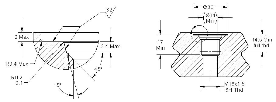
ISO 1649-1 M18 Port
Before insertion of the sensor, the cylinder rod must have a 5/16-inch (8 mm) diameter (minimum) blind hole gun-drilled into it from the piston end that is at least 1 inch deeper than the nominal measuring range of the sensor. Ensure that the material of the cylinder rod is specified to ASG for proper calibration.
If the mechanical details are correct, the cylinder rod should be moved to its fully retracted position. The sensor may then be inserted into the o-ring port and tightened down with a wrench on its hex.
Electrical connections: Connect MR-7 sensors to the electrical system according to the following charts:
4-Conductor Cable | |
I/O Function | Cable Color |
+DC Voltage input | Red |
Ground | Black |
Analog output | Green |
SenSet™ | White |
5- Pin M-12 Connector | Cable | |
I/O Function | Pin | Color * |
+DC Power input | 1 | Brown |
Ground | 2 | White |
Voltage output | 3 | Blue |
Current output | 4 | Black |
SenSet™ | 5 | Grey |
*Cable colors shown are for industry | ||
standard M-12 cord set mating plugs | ||
SenSet: Instructions for the SenSet™ procedure can be found on here. If the SenSet feature is not being used, trim and insulate the end of the SenSet wire or cut it off completely.