
Mechanical installation: An ASG ME-7 in-cylinder position sensors is embedded into a 48 mm diameter
cavity in the rear endcap of a hydraulic cylinder. It may be inserted from the front of an unassembled
cylinder or from the rear of a cylinder with a two-piece endcap with a separate end cover.
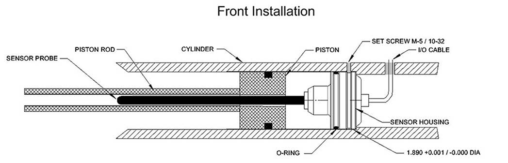
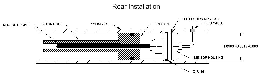
As the drawing shows, the sensor is retained in the endcap with three set screws 120 degrees apart that
fit the groove on the sensor, or with a retaining ring inserted next to the mounted sensor body. Besides
clearance for the sensor's back and an exit hole for the I/O cable, there is also a clearance zone of 1 inch
(25 mm) diameter by 1 inch (25 mm) long required for the front nose of the sensor body body.
Before inserting the sensor, verify that the cylinder rod has a 5/16-inch (8 mm) diameter (or larger) blind
hole that is at least 1 inch deeper than the nominal measuring range of the sensor. Make sure that the
material of the cylinder rod is specified to ASG for proper calibration.
If the mechanical details are correct, the sensor may be inserted into the 48 mm cavity, being careful not
to nick the o-ring, and with the I/O cable routed through its exit hole. Fasten the sensor in place with the
3 set screws or a retaining ring.
Electrical installation: Connect ME-7 sensors to the electrical system according to the following chart:
ME-7 4- Conductor Cable | |
I/O Function | Color |
+DC power input | Red |
Ground | Black |
Analog output | Green |
SenSet™ | White |
SenSet: instructions for the SenSet™ procedure can be found here.
If the SenSet feature is not being used, trim and insulate the end of the white wire or cut it off completely.
Application Notes Categories