Linear Position Sensor FAQ

How do I match the full scale electrical output of a sensor to the actual mechanical movement range of the device?

Calibrating Alliance Sensor’s LVITs with SenSet™ Field Programmability


Please note that your LVIT sensor is calibrated at the factory to a specific measuring range.  You may choose to retain this calibration if it fits your purpose, or you may choose to recalibrate your sensor using the SenSet™ feature if you desire a more precise match of the sensor’s electrical output to your mechanical device’s range of movement.

Alliance Sensors’ LVIT Linear Position Sensors feature SenSet Field Programmability, which allows the installer to very simply and quickly match the full scale electrical output of a sensor to the actual mechanical range of movement of the device in which the sensor is installed. This type of activity is usually referred to as field calibration. To proceed with SenSet field calibration, follow these instructions:

1.  Install the sensor into your mechanical device, leaving the sensor’s I/Os unconnected.

2.  Connect the black wire or ground terminal to power (-), and then connect the correct DC power input (+) to the sensor via the red wire or + power terminal.

3a. To begin the SenSet process for voltage output, connect a DC voltmeter having an appropriate range with its plus (+) test lead connected to the green wire or output terminal, and the meter's (-) test lead connected to the black wire or ground 

 3b. To begin the SenSet process for current loop output, connect a DC milliammeter having an appropriate range with its plus (+) test lead connected to the green wire or output terminal and its minus (-) test lead connected to the loop load resistor, typically 250 or 500 Ohms. Connect the other end of the loop load resistor to the black wire or ground.

4.  Extend your mechanical device to the point of its full range of motion; then connect the white (cal) wire or cal terminal to the black wire or ground terminal for at least 3 seconds.

5.  Fully retract the mechanical device to its zero (start) position; then connect the white (cal) wire or cal terminal to the black wire or ground terminal for at least 3 seconds.

6. The sensor’s output will now be calibrated to the end points of your mechanical device.  The SenSet procedure can be redone without limit, but its operational range is limited to 20% of specified full range, both at zero and at full range. (0 to 20% around zero, and 80 to 100% around full range)  Note that both ends of the sensor’s range must be calibrated using the SenSet procedure for the process to take effect.

7. In the event of a problem, the sensor can be reset to its original state before SenSet was attempted by connecting the SenSet white wire or terminal to the black wire or ground terminal for at least 30 seconds.

8. When the SenSet process is complete, disconnect the voltmeter, or, in the case of current loop output, disconnect the milliammeter and reconnect the loop load to the green or output terminal.  If you are using a leaded or cable output sensor, you may wish to trim and insulate the end of the white (cal) wire to avoid an inadvertent recalibration.

Questions? Call an application engineer at 856-727-0250 or send us a message by clicking here.


LVIT Technology --- What is it and where does it fit into the sensor world?

What is LVIT Technology? LVITs, Linear Variable Inductive Transducers, have been around for more than 30 years, and are becoming very popular due to their relatively low cost and flexibility to be packaged in many different forms. LVITs are contactless position sensing devices that utilize eddy currents developed by an inductor in the surface of a conductive movable element to vary the resonant frequency of an L-C tank circuit. The most common form of an LVIT uses a small diameter inductive probe surrounded by a conductive tube called a “spoiler” that is mechanically coupled to the moving object. Typical LVITs have full ranges from fractions of an inch to 30 or more inches. Modern electronics using microprocessors and small component size makes outstanding performance possible, achieving linearity errors of less than ±0.1% and temperature coefficients of 50 ppm/ºF, along with either analog or digital outputs. The range of housing sizes for LVITs can be seen in Figure 1 and a cutaway view of an LVIT can be seen in Figure 2.


LVIT Linear Position Sensors

 
Figure 1


LVIT LR-27 Linear Position Sensor

 
Figure 2

LVITs are found in a wide variety of different applications that require position information or feedback. Typical LVIT applications include mobile hydraulics, subsea hardware, civil engineering testing, power generation and energy development, and factory automation.

In mobile hydraulics the LVIT is commonly used to measure hydraulic or pneumatic cylinder position. Usually the sensor has a pressure-sealed head and a probe long enough to insert into a gun-drilled hole in the cylinder’s ram. The ID of this hole in the ram then acts as the spoiler. The sensor head can either be port mounted or embedded into the end cap of the cylinder. A typical in-cylinder LVIT installation is shown in Figure 3.


LVIT MR Series Linear Position Sensor

 
Figure 3

This packaging fulfills many different applications in mobile hydraulics such as bulldozer shovel or snow plow positioning, boom positioning on hydraulic cranes and manlifts, and in a variety of agricultural vehicle accessory position feedback requirements.

For subsea cylinder applications involving pumps, chokes, blowout preventers, and ROV-based actuators, the LVIT is designed to withstand the internal and/or external pressures of a PBOF (pressure balanced, oil filled) system. Other technologies commonly used to satisfy these applications require additional hardware like a ring magnet to operate, which adds cost to the machining of the cylinder ram and complexity to the installation. Typical subsea LVITs are shown in Figure 4.


LVIT MHP Series Linear Position Sensor

 
Figure 4

Typical civil engineering applications include measuring bridge expansion and contraction due to seasonal heating and cooling, and related shifts in trunnions and roller support mechanisms. This problem of expansion and contraction is compounded with railway bridges and trackage, where the expansion of a mile-long section of rail could be as much as 4 feet over a change of temperature in some climates of 100 degrees F. This could lead to rail buckling, known in the industry as “sun kink,” and the derailment of a train. In this type of application, instead of having a bare probe protruding from the sensor head, the LVIT’s probe coil, spoiler, and electronics are packaged inside of a cylindrical housing for heavy duty protection, allowing the sensor to be exposed to its environment. The LVITs are connected to the pier and deck of the bridge to measure the relative position of the two, or directly to the rails to measure rail buckling. LVIT technology is extremely robust and so can withstand seasonal weather conditions such as heat, cold, rain, and snow. An example of an installation of heavy duty LVITs on a bridge is shown in Figure 5.


LVIT Linear Position Sensor on Bridge

 
Figure 5

LVITs are used in many factory automation applications, including packaging and material handling equipment, die platen position in plastic molding machines, roller position and web tension controls in paper mills or converting facilities, and robotic spray painting systems. Being contactless, the basic measurement mechanism of an LVIT does not wear out over time. LVITs also do not have the higher installed cost associated with other contactless technologies.

LVITs are being utilized in specific areas of the energy sector. In power generation applications, LVITs are used for valve position feedback, feedwater pump displacement, or generator shell movement. In oil fields, LVITs are used in hydraulic-operated pumps that replace Lufkin-style pump jacks, and to measure the poppet position inside check valves.

Alliance Sensors Group’s LVIT product line is offered with ASG’s proprietary SenSet™ field programmable scaling, which allows a user to adjust for mechanical variations after installation in the application simply by pushing a button or grounding a connection. This SenSet™ feature reduces setup time and cost of ownership. For example, SenSet™ allows a rising stem valve that opens 9.5 inches to be coupled to a 10-inch range LVIT and get full scale output over the 9.5 inches by scaling the sensor’s output after it has been installed.

From the foregoing exposition, it is apparent that LVITs represent a valuable and cost-effective position measuring technology for a broad range of applications.


What's So Good About LVIT Technology and What Is It All About, Anyway?

Alliance Sensors Group, a division of H.G. Schaevitz, LLC, has developed a linear position sensing technology called LVIT that offers an excellent price-to-performance ratio compared to other linear position sensing technologies such as LVDTs, linear potentiometers, and magnetostrictive devices. Furthermore, LVITs can offer the best stroke-to-length ratio of any contactless linear position sensor, because their overall length only increases by a relatively small percentage beyond their stroke.


So, the answer to the title question: What's So Good About LVIT Technology is summarized as follows:


- Excellent price-performance ratio compared to other common linear position sensors 

- Superior stroke-to-length ratio compared to other contactless linear position sensors 

- Contactless, frictionless operation with no components to wear out and no ring magnet

- Extremely robust to environments as a result of ruggedized construction and materials

- Many sensor sizes and configurations for different position sensing applications

- Pressure sealed sensors for fluid power applications, including in-cylinder position

- Less expensive than LVDTs and more reliable than in-cylinder potentiometers


LVIT


To find out more about this technology read on below. 


Block Diagram LVIT Linear Position Sensor


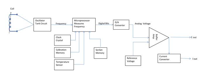
Block Diagram of Major Operating Features

The acronym LVIT stands for Linear Variable Inductance Transducer. Because LVITs are inductive, they are contactless devices with no friction issues or moving parts that can wear out. As is common for inductive sensors, they exhibit outstanding repeatability, with resolution limited only by the electronics used with them. LVITs offer the performance of contactless sensors like LVDTs or magnetostrictive sensors at a price comparable to industrial grade linear potentiometers.

They are DC in-DC out sensors constructed with built-in smart electronics that has relatively low power consumption, typically much less than one Watt. Because the basic sensor of an LVIT is extremely repeatable, an on-board microprocessor can be used to linearize the sensor's output signal and apply temperature compensation to the system using a built-in temperature sensor. This linearization process yields typical linearity errors of ≤ 0.1% of Full Scale Output (FSO), depending on the number of data points used for the sensor's calibration.

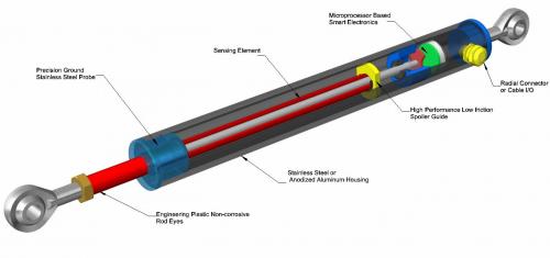
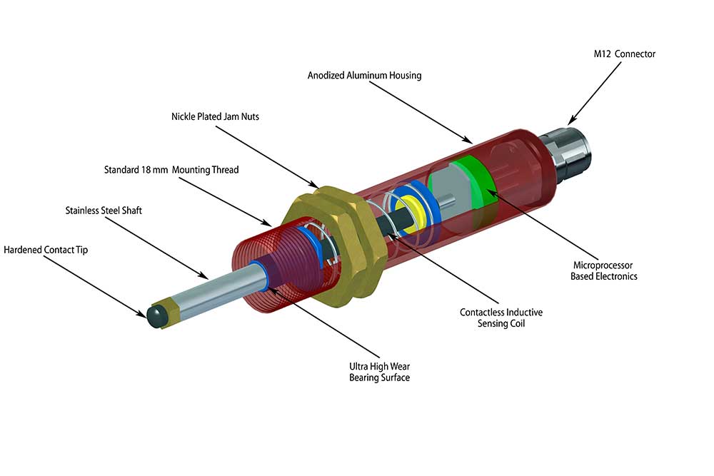
An LVIT sensor uses a long, small-diameter probe coil that is connected into the resonant tank circuit of an oscillator in the built-in electronics. A conductive tube moved over the coil changes its inductance and the resonant frequency of the tank circuit. Oscillator output is coupled to a 12-bit microprocessor in the on-board electronics to measure its frequency. The digital output of the microprocessor then goes to a digital-to-analog converter which develops a voltage proportional to frequency that is conditioned to produce a high level analog DC output from the sensor. The 12-bit microprocessor also determines the resolution of an ASG LVIT position sensor, which is 0.025% of FSO.

One reason for the robustness of LVITs is that the probe coil is wound on a glass-filled thermosetting plastic rod which can survive large deflections without fracturing. Its single coil winding makes only two connections with the electronics, which substantially reduces the likelihood of a failure and enhances reliability. The built-in electronics is completely potted within its housing, so these sensors can sustain high shock and vibration levels. This robustness, coupled with a normal operating temperature range of -20 to 85 C, and an extended operating temperature range of -40 to 105 C, permits an ASG LVIT to function very well in practically any industrial or commercial environment. In special cases where an LVIT might be required to operate in a higher temperature environment, the sensor's electronics may be located in a more benign environment a short distance away from the sensor's probe assembly.

Another reason for an LVITs' robustness is that the sensors' housings are made of heavy wall anodized aluminum or stainless steel and are environmentally sealed to IEC IP-67 or IP-68. The LVITs' operating rods (spoilers) are also stainless steel, and do not easily bend as happens with some other sensors.

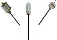
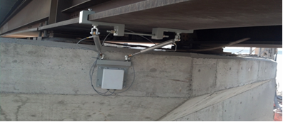
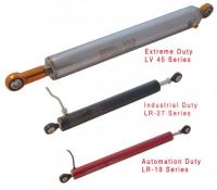
ASG offers several series of LVITs with industrial duty housings and operating rods having swivel rod ends for use in typical factory automation applications such as packaging machinery, gates for sorting chutes, press brakes, and automatic assembly test stands. Other series of LVITs are offered with extra heavy duty housings to operate in such severe environments as mining machinery, off-road equipment, rail or road bridge motion monitoring, road construction equipment, snow plows, and garbage haulers.

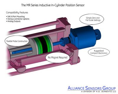
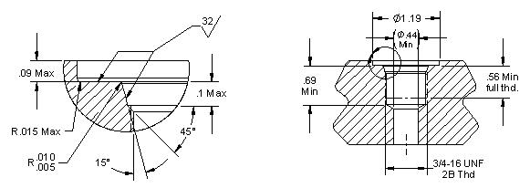
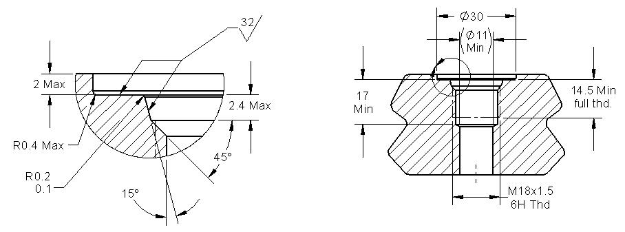
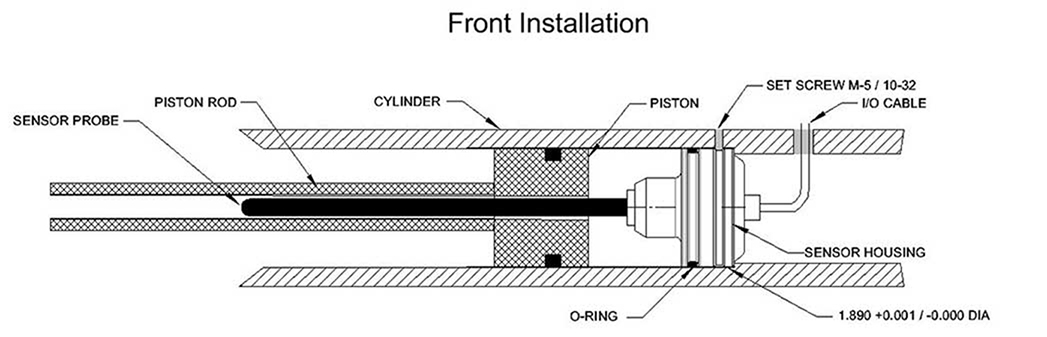
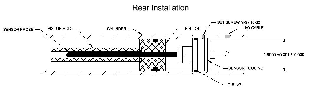
Still other configurations available from ASG include sensors specifically made for operation to 5000 psig in hydraulic cylinders, either for port mounting externally or for embedding internally in the cylinder. For these in-cylinder applications, the cylinder rod or ram is gun-drilled with a hole in clearance of the probe coil, which then becomes the spoiler tube for the sensor. There is no need to machine a cavity in the piston for the magnet of a magnetostrictive device or for the spool of an in-cylinder potentiometer.

Besides the LVIT sensors for use in hydraulic cylinders, other pressurized sensors can be built for subsea applications at depths of 12,000 feet in a PBOF environment. There are also short stroke LVITs that operate in a pressurized fluid environment to provide spool position feedback in two-stage electro-hydraulic proportional or servo valves. In this application, the LVIT probe goes into a blind hole in one end of the main spool, which greatly simplifies installation and eliminates any need to mechanically couple a position sensor to the spool.

One valuable feature built into ASG LVITs is a proprietary process called SenSet; which gives a user the ability to match the end points of the sensor's analog output with the ends of the range of motion of a workpiece or the ram of a hydraulic cylinder to which the sensor is attached. This SenSet™ feature permits a user to optimize the position measuring system's resolution over its full range of motion.

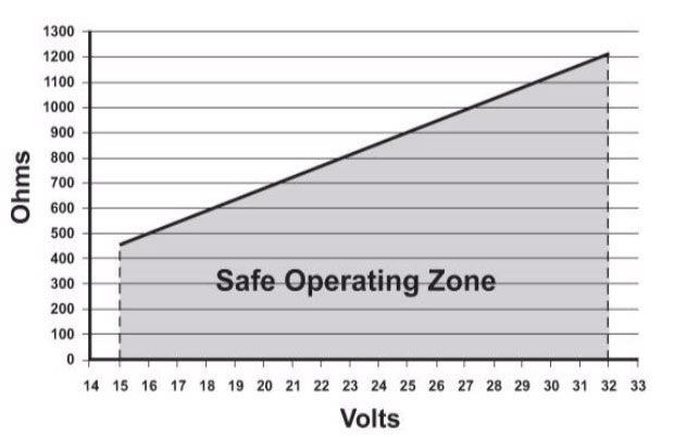
ASG LVITs are offered with various connector or cable terminations in axial or radial configurations and can measure full ranges from fractions of an inch to 40 inches, with a resolution of 0.025% of full scale output. Operating from DC power inputs of 5 to 24 Volts, standard LVIT analog outputs include several high level DC voltages and 4-20 mA DC sourcing. Being digital devices, LVIT dynamic responses are shown as update rates, which nominally range from 250 to 500 Hz, depending on the LVIT series.

View Most Commonly Used LVITs Here! 

View Most Commonly Used In-Cylinder Position Sensors Here! 


How do I calibrate your linear position sensor using SenSet® field programmability?

Calibrating Alliance Sensor’s LVITs with SenSet™ Field Programmability


Please note that your LVIT sensor is calibrated at the factory to a specific measuring range.  You may choose to retain this calibration if it fits your purpose, or you may choose to recalibrate your sensor using the SenSet™ feature if you desire a more precise match of the sensor’s electrical output to your mechanical device’s range of movement.

Alliance Sensors’ LVIT Linear Position Sensors feature SenSet Field Programmability, which allows the installer to very simply and quickly match the full scale electrical output of a sensor to the actual mechanical range of movement of the device in which the sensor is installed. This type of activity is usually referred to as field calibration. To proceed with SenSet field calibration, follow these instructions:

1.  Install the sensor into your mechanical device, leaving the sensor’s I/Os unconnected.

2.  Connect the black wire or ground terminal to power (-), and then connect the correct DC power input (+) to the sensor via the red wire or + power terminal.

3a. To begin the SenSet process for voltage output, connect a DC voltmeter having an appropriate range with its plus (+) test lead connected to the green wire or output terminal, and the meter's (-) test lead connected to the black wire or ground

 3b. To begin the SenSet process for current loop output, connect a DC milliammeter having an appropriate range with its plus (+) test lead connected to the green wire or output terminal and its minus (-) test lead connected to the loop load resistor, typically 250 or 500 Ohms. Connect the other end of the loop load resistor to the black wire or ground.

4.  Extend your mechanical device to the point of its full range of motion; then connect the white (cal) wire or cal terminal to the black wire or ground terminal for at least 3 seconds.

5.  Fully retract the mechanical device to its zero (start) position; then connect the white (cal) wire or cal terminal to the black wire or ground terminal for at least 3 seconds.

6. The sensor’s output will now be calibrated to the end points of your mechanical device.  The SenSet procedure can be redone without limit, but its operational range is limited to 20% of specified full range, both at zero and at full range. (0 to 20% around zero, and 80 to 100% around full range)  Note that both ends of the sensor’s range must be calibrated using the SenSet procedure for the process to take effect.

7. In the event of a problem, the sensor can be reset to its original state before SenSet was attempted by connecting the SenSet white wire or terminal to the black wire or ground terminal for at least 30 seconds.

8. When the SenSet process is complete, disconnect the voltmeter, or, in the case of current loop output, disconnect the milliammeter and reconnect the loop load to the green or output terminal.  If you are using a leaded or cable output sensor, you may wish to trim and insulate the end of the white (cal) wire to avoid an inadvertent recalibration.

Questions? Call an application engineer at 856-727-0250 or send us a message by clicking here.


How do I Install In-cylinder MR-7 Position Sensors?

Mechanical installation: MR-7 in-cylinder position sensors are designed to be inserted into an o-ring port machined into the rear endcap of the hydraulic cylinder.  Standard MR-7s use an SAE J1926-1 -8 port with a 3/4-16 UNF thread. Metric threaded versions use an ISO 1649-1 port with a M18 x 1.5 thread. Both ports are Illustrated below.  For either size port, the sensor's male thread comes with a Viton o-ring installed.

SAE J1926-1  -8 Port

MR-7 Series 8 Port

ISO 1649-1 M18 Port

MR-7 Series M18port


Before insertion of the sensor, the cylinder rod must have a 5/16-inch (8 mm) diameter (minimum) blind hole gun-drilled into it from the piston end that is at least 1 inch deeper than the nominal measuring range of the sensor. Ensure that the material of the cylinder rod is specified to ASG for proper calibration.

If the mechanical details are correct, the cylinder rod should be moved to its fully retracted position. The sensor may then be inserted into the o-ring port and tightened down with a wrench on its hex.

Electrical connections: Connect MR-7 sensors to the electrical system according to the following charts:

 4-Conductor Cable

I/O Function

Cable Color

+DC Voltage input

Red

Ground

Black

Analog output

Green

SenSet™

White

 5- Pin M-12 Connector

Cable

I/O Function

 Pin

Color *

+DC Power input

1

Brown

Ground

2

White

Voltage output

3

Blue

Current output

4

Black

SenSet™

5

Grey

*Cable colors shown are for industry

standard M-12 cord set mating plugs


SenSet: Instructions for the SenSet™ procedure can be found here. If the SenSet feature is not being used, trim and insulate the end of the SenSet wire or cut it off completely.


How do I Install In-cylinder ME-7 Position Sensors?
Mechanical installation: An ASG ME-7 in-cylinder position sensors is embedded into a 48 mm diameter
cavity in the rear endcap of a hydraulic cylinder. It may be inserted from the front of an unassembled
cylinder or from the rear of a cylinder with a two-piece endcap with a separate end cover.
 
 
ME-7 Front Install


ME-7 Rear Install


As the drawing shows, the sensor is retained in the endcap with three set screws 120 degrees apart that
fit the groove on the sensor, or with a retaining ring inserted next to the mounted sensor body. Besides
clearance for the sensor's back and an exit hole for the I/O cable, there is also a clearance zone of 1 inch
(25 mm) diameter by 1 inch (25 mm) long required for the front nose of the sensor body body.
Before inserting the sensor, verify that the cylinder rod has a 5/16-inch (8 mm) diameter (or larger) blind
hole that is at least 1 inch deeper than the nominal measuring range of the sensor. Make sure that the
material of the cylinder rod is specified to ASG for proper calibration.
If the mechanical details are correct, the sensor may be inserted into the 48 mm cavity, being careful not
to nick the o-ring, and with the I/O cable routed through its exit hole. Fasten the sensor in place with the
3 set screws or a retaining ring.
 
Electrical installation: Connect ME-7 sensors to the electrical system according to the following chart:
 
ME-7 4- Conductor Cable
I/O Function  Color
+DC power input  Red
Ground  Black
Analog output  Green
SenSet™  White
 
 
SenSet: instructions for the SenSet™ procedure can be found here.
If the SenSet feature is not being used, trim and insulate the end of the white wire or cut it off completely.


How do I minimize ground loop issues for sensors with a common I/O ground?

Concerns about the effects of a common ground on the individual outputs from multiple ASG’s LVIT sensors can be remedied by using a single ground point. This ground point, which should be made at the input ground of electronics used to monitor or measure the sensors’ outputs. This is where the power ground/output ground lead for each of the sensors is connected along with the power supply’s ground. Separate connections are used for each sensor’s power positive and output. By connecting sensors in this manner, variations in the ground currents or output currents of individual sensors are not combined into the outputs of any other sensors in the system. This grounding connection approach obviates the need for isolated outputs and is the universally recommended grounding practice for minimizing ground loop issues. However, if a customer is unable to make the recommended grounding connection, multi-channel isolation modules are available from several sources at relatively low cost per channel.

Need technical help with your measurement application? Call us today 856-727-0250 or send us a message by clicking here.

How do I Connect to Alliance Sensors Group’s current loop output LVIT sensors

Alliance Sensors Group, a div of H. G. Schaevitz LLC, Moorestown, NJ, USA, makes position sensors utilizing Linear Variable Inductance Transducer (LVIT) technology which offer analog outputs of both voltage and current loop, the most common of which are 0 – 10 Volts DC and 4 – 20 mA DC. A voltage output is typically used in applications that have a receiving device, i.e.: PLC, DAQ system, or readout, located close by so the interconnecting wiring is not very long and can be shielded if necessary to prevent noise or EMI being coupled into the output.

A current loop consists of a 4-20 mA transmitter, a receiver with a loop load resistor across its input, the loop DC power source, and the interconnecting wiring for all these devices wired in series. ASG products with current loop output are 3-wire sourcing transmitters, whereby the loop and transmitter power comes from outside the loop but they share a common ground within the current loop.

There are several significant advantages to using a 4-20 mA DC current loop to transmit data over long lines from a sensor to a DAQ or control system instead of a voltage output. First of all, the current in the loop originates from a low source impedance, so the signal is much less susceptible to induced noise and electromagnetic interference (EMI) than any voltage signal. Current loop wiring typically can use twisted pair cables which often don’t require shielding. Second, there is no degradation of the signal or losses over long connecting lines from line resistance, which will happen with a voltage signal. Third, it is usually possible to insert some other current-sinking device for example, a local current readout, into a current loop by simply connecting it in series within the loop.

A major benefit of a 4-20 mA output is the “live zero” at the 4 mA point (0% of the measured quantity) so the loss of a current, i.e.: 0 mA, would indicate a malfunction in the loop, typically a break in the wiring or a disconnected device, and thereby is a fail-safe system diagnostic. Furthermore, an out-of-range loop current lower or higher than some specified value would indicate a malfunction in the system’s electronics, providing an additional system diagnostic.

Using current loop output requires more care overall than a voltage output ordinarily would. 3-wire transmitters are current sourcing, which means they drive current into the loop using DC power coming from the transmitter, so they must always connect to a sinking receiver input, where a loop load resistor is the only element involved; there is no DC power available from the input terminals of the receiving device. It is very important to never connect a 3-wire transmitter to a receiver input configured to work with a 2-wire or loop-powered transmitter because the 3-wire transmitter may be seriously damaged.

For any specified loop voltage, there is a maximum loop resistance that will permit full current to be developed in the loop. Exceeding the maximum loop resistance, which always includes the resistance of the field wiring, prevents the system from driving the full 20 mA (or higher) current into the loop. The loop load graph for a typical 3-wire current loop output sensor is shown in Figure 1. At 24 Volts input, the recommended power supply for ASG sensors and modules, the total loop resistance can be as high as 850 Ohms.

Loop Output Figure 1


Figure 1 Maximum loop resistance vs. input voltage for a typical 3-wire current loop.

Loop load resistance is usually dependent on what voltage the receiver system input requires for good resolution. A 4-20 mA loop current will develop 2-10 VDC across a 500 Ohm load resistor (E = IR). If the receiver system works satisfactorily with a lower input voltage, a 4-20 mA loop current will develop 1-5 VDC across a 250 Ohm load resistor. Both are common loop loads that are often built into the receiving device’s input terminal connections.

The loop load resistor power rating and its temperature coefficient must be chosen to ensure that any heating caused by current flowing through the resistor does not change the resistor's value and thereby change the voltage developed across it. For a 500 Ohm loop load resistor, the power dissipated at 20 mA is 0.2 W (P = I2R). A good choice for the load resistor's power rating is at least 2 watts, preferably 3 Watts. The resistor will not heat up much, even at full 20 mA loop current, so there shouldn’t be any voltage change across the load resistor due to its power dissipation instead of loop current changes.

Connecting a 4-20 mA current meter directly to a sensor’s current output terminals is a poor practice which is to be discouraged, but a feature of ASG’s current loop output sensors is that they are capable of operating with a current shunt across their output. They will survive and continue to operate with what effectively amounts to a short circuit across their current output.

As noted earlier, the lack of current in the loop is a self-diagnostic that indicates interruption of the series loop. The most likely causes are a disconnected loop device, a break in the loop wiring, or a blown fuse in the DC power supply. It is also possible that a loop device failed in an open-circuit mode. If the loop current drops to a non-zero value below 3.6 mA, it suggests a failure in either the transmitter, the loop power supply, or the loop load resistor. If the loop current were to rise above 20.5 mA, the cause is likely to be a transmitter short circuit failure.

Where Can I find Datasheets for your LVIT Products?


LVIT Linear Position Sensors DataSheets


Need technical help with your measurement application? Call us today 856-727-0250 or send us a message by clicking here.

Why is the New LVIT Technology is so Important for Linear Position Measuring?

There has been a revolution in the position sensor market with the development of low cost, high precision, inductive LVIT Technology developed by H. G. Schaevitz LLC dba Alliance Sensors Group. 

LVIT Technology (Linear Variable Inductive Transducer) has significant advantages over LVDTs and Potentiometers having an excellent stroke-to-length ratio and using contactless, inductive technology; giving you best of all worlds at a cost-effective price. The LRS-18 series are designed for dimension or position measuring applications in factory automation and in various industrial and commercial applications such as automotive testing, mil/aero test stands, robotic arms, and packaging equipment.


LRS-18 Spring Loaded LVIT


The new LRS-18 series of spring-loaded LVITs have the following features:
  • - EXCELLENT stroke-to-length ratio
  • - Contactless operation
  • - Ranges from 12.5 to 100 mm (0.5 to 4.0 inches)
  • - M18 x 1 threaded housing
  • - IP67 sealed
  • - Corrosion resistant, anodized aluminum or stainless steel body
  • - Connector or cable terminations
  • - A variety of analog I/Os
  • - SenSet™ field programmability


The LRS-18 was designed with a focus on automation machinery and is constructed with an industry standard M12 connector and a M18 threaded body complimented by a spring-loaded, stainless steel probe shaft in an ultra-high wear bearing system with a contactless inductive sensing coil connected to microprocessor based electronics, encased in a corrosion resistant housing.