Blog
Part 1
Linear position measurement is a frequent requirement for many industrial automation or process control systems, QA functions, and R&D testing. The actual position measurement function is normally done by some type of position sensor, the selection of which quite often is based on just a few key specification parameters and its purchase cost. However, using the sensor’s purchase cost for economic guidance can be very misleading. The real cost of utilizing that sensor must be considered based on installation costs, operational costs over the period of time it is in service, maintenance and recalibration costs, operator training, and possible replacement cost. When taken together, these costs, along with several other expenses which will be identified later in this article, add up to the True Cost of Ownership or TCO.
This series of articles will help you to evaluate the TCO of commonly used linear position sensors. The first article identifies the most commonly utilized industrial position sensing technologies and poses a set of questions to ask yourself about various position sensor application issues to assist you to make an optimum choice of sensor from both a technical and an economic perspective. The second article starts by examining the strengths and weaknesses of these technologies, presents a comparison chart of their specification parameters with a brief explanation of what those specifications mean, and helps to focus on the technical aspects involved in TCO evaluation. The third article pulls together the answers about costs derived from the answers to the queries in the initial article, combines that information with the choices made as a result of the examination of sensor technologies and the weighting applied to the specifications parameters in the second article, and shows how these factors combine into the TCO.
The most commonly utilized industrial position sensing technologies incorporate a moving element which is attached to the object or workpiece whose position is being measured, while the body of the sensor is fixed in position. Typical of these are Linear Variable Differential Transformers (LVDTs), Linear Variable Inductance Transducers (LVITs), Magnetostrictive Linear Displacement Transducers), (MLDTs, also known as LDTs), and Linear Resistance Potentiometers (POTs). And while these sensors all operate on different physical principles, they are all analog output sensors. There is another style of linear position sensor that has a digital output, glass scale encoders, but their use is largely limited to the machine tool and CMM markets primarily because they are not considered robust enough for the majority of industrial automation or mobile hydraulics applications.
Some position sensing technologies function without requiring any physical contact with the object whose position is being measured, and are often called “non-contacting” position sensors. Typical examples are proximity, ultrasonic, laser, radar, optical, and similar sensors. However, these types of sensors all have drawbacks that can limit their use, such as specific target materials required for proximity, environmental effects on ultrasonic, high initial cost as well as the eye protection requirement for lasers, etc. For these reasons, non-contacting position sensing technologies will be excluded from the focus of this article. Of the four common sensor technologies, the first three are “contactless”, that is, they do not require any physical or electrical contact between their moving element and their fixed part. Pots, however, do have a wiper that contacts their internal resistance element that is fundamental to their operation, so they are not contactless. The foregoing explanation should illustrate the difference in the meaning of “contactless” and “non-contacting” as applied to position sensors.
All four sensor technologies will be described in detail in the second article of this series. But before comparing and contrasting the details of these common industrial position sensing technologies, there are a number of questions you should answer to assist you in choosing the optimum sensor for your application from among them.
Can you define explicitly what are you attempting to accomplish with the position measurement?
While this may seem to be an obvious step, it is often overlooked during a sensor selection process and is critical to developing an overall perspective. Once you answer this question, other questions pertaining to the details of the measurement can be posed.
What is the nature of your sensing application?
Typical answers include automation or control systems, industrial process monitoring without automatic control, product quality assurance, and R&D lab testing. Your response will help formulate the weighting of priorities that you should apply to the specification parameters of the sensors under consideration. For example, an automatic control system would likely require better dynamic response than a typical quality assurance test, but quality assurance measurements usually requires better measurement precision and especially calibration traceability.
In what environment is the sensor expected to operate and how harsh is it?
There are many issues involved in answering this question. One is the range of ambient temperatures in which the sensor will be expected to operate. Another is the level of vibration and/or shock which the sensor will experience. A key issue is the degree the sensor will be exposed to moisture, coolant mists, solvent or chemical vapors, and dust or grit. For example, in a typical factory floor environment, there can be serious shock impulses transmitted from the structures of punch presses and a large amount of grit that can accumulate from sanding or finishing operations. Is there possible electromagnetic interference (EMI) from arc welders, variable frequency motor drives, or 2-way radios? Finally, is the sensor going to be operating in a hazardous location that would require a UL, FM, or CSA hazloc-approved component?
What reliability and quality issues apply to the position sensor?
Several important factors pertain to this topic, the most important of which is whether the sensor is being used in a safety-critical application where its failure could result in serious injury to personnel. In such an application, reliability becomes the highest priority in selecting the right position sensor technology. For less critical uses, the key quality questions relate to the measurement system’s duty cycle and expected service life. Reliability comes into sharp focus when the sensor must operate on a 24/7/365 duty cycle that can cause sensor system operating cycles to accumulate very quickly and wear out to develop in a relatively short period of time.
Another factor pertaining to reliability is the frequency of recalibration required for the position sensor, as well as its preventative maintenance program. Downtime of the position measuring system, whether it is scheduled or unscheduled, typically has a significant cost beyond the direct expenses of recalibration or maintenance. Replacing a worn out or failed sensor also can introduce downtime of substantial cost.
Are there any additional items needed to make the position sensor function?
Typical examples are ancillary electronics like power supplies, signal conditioners, and various cables. An often overlooked extra is the need for specific mounting hardware and the labor for installing the sensor. A further requirement could be special software that must be acquired to effectively utilize the sensor.
Is there any special training or a sensor- dependent learning curve for the measuring system operator?
This is usually the most common unanticipated issue in applying a sensor in a measuring system. If this is a potential expense, then it is necessary to consider it in developing a budget for the real installed cost of the position sensor in the measuring system.
What position measurement accuracy and resolution are actually required for your application?
It is quite possible for the position sensor in a measuring system to be over- specified in these regards, which can add unnecessary difficulty in making the choice of the optimum sensor from among the many technologies available and certainly can add cost. The key to this issue is a good understanding of what these parameters mean, which will be explained in the second article in this series. Then you should evaluate the effect of lower accuracy and/or resolution for the position measurement application by doing the necessary calculations. In performing these calculations, pay particular attention to the exact manner in which the specification is presented. Unfortunately, it is possible for a sensor manufacturer to utilize specmanship that favors their product and can lead to misunderstanding unless the parameter is closely scrutinized.
The foregoing questions assist in the selection of the correct sensor so that a prospective position sensor user or specifier will gain insight into various factors. These factors go into the choice of a position sensor for a measurement application and can establish a weighted priority list of specification parameters for the optimum sensor choice that uses the information derived from the answers or responses to these questions. The next article in this series continues with a more detailed technical explanation of the strengths and weaknesses of the four technologies cited above, accompanied by a comparison chart of the significant specifications and parameters, along with a brief explanation of the meaning of these specifications. Then the third article delves into all the cost factors that make up the true installed cost of a position sensor and how you can assimilate the results into a TCO of the position measuring system.
Part 2
To help you evaluate the True Cost of Ownership (TCO) of commonly used industrial linear position sensors, our first article identified the four most commonly utilized industrial position-sensing technologies. It also posed questions to ask yourself about various position-sensor application issues to assist you in making an optimum choice of sensor from a technical and an economic perspective.
Our second article examines the strengths and weaknesses of these technologies, presents a comparison chart of their specification parameters together with a brief explanation of what those specifications mean, and helps you to focus on the technical aspects of a TCO evaluation.
The most commonly utilized industrial position sensing technologies are linear variable differential transformers (LVDTs), linear variable inductance transducers (LVITs), magnetostrictive linear displacement transducers (MLDTs, also known as LDTs), and linear resistance potentiometers (POTS).
Linear Resistance Potentiometers (POTS)
POTS are simple position sensors that move a sliding contact along a fixed linear-resistance element inside an enclosure. The object whose position is going to be measured is coupled to a shaft attached to the slider. The ends of the resistance element are connected to low-voltage dc and the pot acts as a voltage divider. An output voltage proportional to the slider position is developed between the slider connection and one end.
Typically, the resistance element is made of a conductive polymer, but the use of a contacting slider makes a pot susceptible to shocks, vibration, and wears out. For this reason, applications use POTS that don’t require long service life.
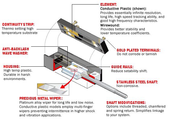
The attractions of POTS are their ease of hook up and relatively low cost. POTS with polymer resistance elements generally offer good linearity, resolution, and repeatability to begin with, but their repeatability typically suffers degradation with increasing numbers of cycles of operation. POTS also have excellent stroke-to-length ratios, but they can be easily broken or severely damaged in the event of a mechanical overload. POTS usually are limited in their analog output to a dc voltage equal to or less than their input voltage. The chart in this article compares potentiometers with other position-sensing technologies.
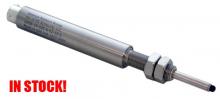
Magnetostrictive Linear Displacement Transducers (MLDTs)
Magnetostrictive linear displacement transducers operate by measuring the time it takes a mechanical torsion pulse wave to travel along a waveguide made of a magnetostrictive metal. Thus, an MLDT is a time-of-flight (TOF) sensor system like radar or sonar. Torsion pulse can be generated or detected in several ways, all of which rely on the interaction of the field of a permanent magnet mounted on the moving object with the magnetostrictive waveguide.
In operation, measuring the time interval from when the pulse was launched until it’s reflected back can be accomplished with high accuracy. Thus, an MLDT can offer a relatively high precision position measurement. Although they display excellent resolution, repeatability, and linearity, MLDTs typically have a dead zone at either end of their range, which results in reduced stroke-to-length ratio.
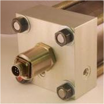
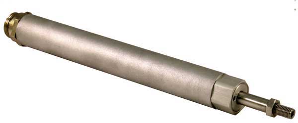
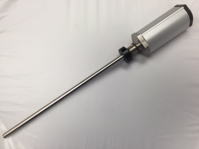
MLDTs are much more costly than other industrial position-sensor technologies for a similar range. Consequently, applications use them where measurement precision is an overarching requirement. Their most common form factor is a small-diameter, sealed, stainless-steel tube, typically 10 mm, welded to a larger metal enclosure that contains the electronics needed to operate the sensors, with a ring magnet assembly over the tube as the moving element. The sealed enclosures’ male O-ring port thread permits their usage in a hydraulic cylinder with a suitable O-ring boss at one end (embeddable versions are available, too).
Like the previously discussed position sensors, MLDTs are contactless, so they do not wear out. However, their internal waveguide is suspended within their tubular probe and is susceptible to effects from shock and vibration, which can impact their reliability and service life. They also have a limited update-rate capability, because the TOF measurement must allow enough time for the pulse to travel to, and be detected at, the maximum range. The chart shows the comparative strengths and weaknesses of MLDTs.
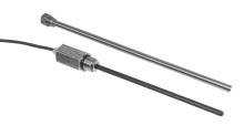
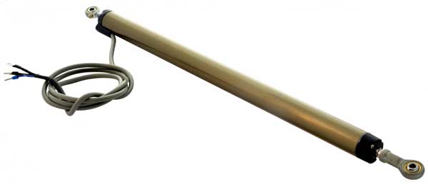
An LVDT is a primary helically wound transformer with a primary and two identical secondary transformers. As an electrical transformer, it operates from low-voltage ac at an audio frequency. A cylindrical movable “core” of high-permeability magnetic material couples the primary voltage to the secondaries, which are connected as series opposing. Over a specific range of core motion, the output voltage of the differentially connected secondaries varies linearly with movement of the core.
In operation, the workpiece whose position is being measured attaches to the core, which does not need any mechanical contact with the LVDT coils.. This contactless operation means that an LVDT position sensor doesn’t wear out and is impervious to mechanical overload. LVDTs are characterized by excellent repeatability and resolution, as well as long life and high reliability. LVDTs come in two forms. The first is an AC-LVDT, which is most often used in hostile environments that involve extreme temperatures of 175°C to values higher than 200°C, and high vibration and shock. An example of the latter may be down-hole in drilling oil wells, which utilizes separate remote support electronics located in a more benign environment than the LVDT itself. The second type of LVDT is called a DC-LVDT, which has built-in electronics that accepts dc power input and produces an analog dc output. A DC-LVDT may be more convenient to use in a lot of applications, but the integral electronics also limits the environments—especially ambient temperature—in which it can operate.
One of their drawbacks is their comparatively poor stroke-to-length ratio, which makes the sensor quite long when measuring position changes over a few inches. AC-LVDTs also have a high installed cost because of the need for a separate signal-conditioning module. However, DC-LVDTs are broadly used in all manner of industrial automation and assembly machinery. Their installed cost is moderate, but depends greatly on range.
Both types of LVDTs typically have a hollow tube form factor with a free or captive core, but spring loaded units are offered in short ranges. The table below shows a more complete comparison of both types of LVDTs with the other common industrial position-sensor technologies.
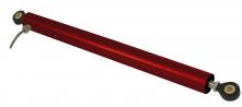
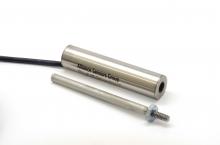
Linear Variable Inductance Transducers (LVITs)
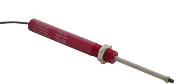
LVITs are similar to DC-LVDTs in that they operate without contact between their inductive probe and their moving element, and they use built-in electronics. But they offer a favorable stroke-to-body length ratio at a significantly lower initial cost than a DC- LVDT.
They operate via changes in the inductance of their probe coil caused by eddy currents in the surface of a conductive moving element called a spoiler, which moves within the inductor’s magnetic field. The integral smart electronics converts the inductance change into an analog dc output.
LVITs offer excellent repeatability along with good resolution and linearity. Their construction and contactless operation enables them to withstand substantial shock and vibration environments, and the internal electronics includes ambient temperature compensation. Because it’s contactless, an LVIT position sensor doesn’t wear out and is resistant to mechanical overload. LVITs come in a variety of configurations for standalone position sensing, or with a pressure-sealed probe to operate inside a hydraulic cylinder that has a gun-drilled blind hole in its ram. The pressure-sealed LVITs have a male O-ring port thread that permits their use in a hydraulic cylinder with a female O-ring boss on one end, or they can be completely embedded inside a cylinder.
The installed cost of an LVIT is low compared to other technologies. Thus, as standalone position sensors, they compete with DC-LVDTs, offering most of the same benefits at much less cost, along with a much better stroke-to-length ratio. They, too, are available in spring-loaded versions for shorter ranges. LVITs also compete strongly against POTS because they offer contactless operation and equivalent stroke-to-length ratios at comparable cost.
Pressure-sealed- probe LVITs compete with MLDTs for use inside of hydraulic cylinders, at lower initial cost and without requiring that the cylinder piston be machined to accept a ring magnet. These specific features lower their installed cost in cylinders for mobile equipment and industrial fluid-power applications. LVITs are compared to the other common industrial position sensors in the table below.
Sensor Inputs and Outputs
One of the often overlooked considerations in selecting an industrial position sensor is the choice of input and output (I/O). Typical sensor inputs are: +24 V dc for devices with integral electronics (DC-LVDTs, LVITs, MLDTs), particularly for automation systems, +10 V dc for POTS, and +5 V dc for many sensors used with embedded microcontrollers.
All of the sensors reviewed offer one or more analog outputs, and a few offer some kind of digital output as well. Utilizing digital outputs usually requires some understanding of network protocols and related issues and the use of specific cabling, which often leads to higher installation costs. Thus, most industrial applications tend to utilize analog outputs.
When the output of the sensor is being input to a PLC or data-acquisition system, dc voltage is the preferred sensor output, especially when the system is located close to the sensor. If the sensor is located some distance from the rest of the system, a 4- to 20-mA current-loop output is often more useful and desirable, but typically requires a 24-V dc power input.
Understanding the Linear Position Sensor Chart
The comparison chart evaluates the important specifications and parameters of the four analog-output position-sensor technologies commonly used in industrial position-measurement applications. The ratings are based on an aggregate assessment of sensors using these technologies, but recognize that specific sensors may differ in some respects.
Range: Many industrial position sensors are offered in full ranges, from fractions of an inch to 20 inches. However, both LVITs and MLDTs are available in longer ranges at modest incremental cost.
Resolution: This is a key parameter in modern measuring systems to indicate the smallest change in a sensor’s input that results in an output change. Although sometimes specified as bits (10-bit resolution equals 1 part in 1024, or 0.1%; 12 bits equals 1 part in 4096, or 0.025%), in analog sensors it’s more often specified as a percentage of full span output (%FSO). Many analog sensors offer infinite resolution, but when used with digital electronics, resolution is limited by the number of bits in the analog-to-digital conversion process. Resolution is one of the two fundamental limiting factors in the application of a sensor, the other limiter being repeatability. Essentially, no sensor can give better performance than its resolution and repeatability permit. Repeatability/Hysteresis: Repeatability is the single-most important specification parameter for a sensor. Repeatability is a measure of the variation in output for repeated trials of exactly the same sensor input applied from the same direction. Its magnitude is determined statistically and usually expressed as a percentage of full range. Hysteresis is a measure of the variation in output at a particular position depending on the direction of motion to that position. Some sensors may have sources of friction, etc. which can introduce hysteresis in its output.
Nonlinearity: Nonlinearity (a.k.a. linearity error) is a measure of the maximum deviation of a sensor’s output from a prescribed straight line, most often a best-fit line. Typically, the reference line is developed by a statistical process (least squares) or drawn between the end points of the output. Smaller linearity error makes it easier to interpret measurements using a sensor calibrated with a limited number of data points, or calibrated only at the end points. With a highly repeatable sensor, digital electronics can be used to linearize a position-measuring system’s output to any desired level within the limit of resolution. Temperature characteristics: Temperature coefficients (tempcos) quantify the deviation of a sensor’s output due to changes in its thermal environment, both hotter and colder. There’s often a tempco for offset, which shifts the sensor is zero point, and another tempco for scale factor, which affects the sensor’s calibration. As noted with nonlinearity, digital electronics can be used with a highly repeatable sensor along with a temperature probe to compensate a measuring system’s output over any reasonable temperature range.
Dynamic response: In a sensor, this may be limited by elements of its mechanical construction, such as inertial mass and friction, or by electronic factors like operating or filter frequency, or by update rate.
Vibration and shock sensitivity: This is determined by a sensor’s mechanical construction, including internal masses. For MLDTs, the waveguide support structure is potentially susceptible to these factors. POTS have potential for wear out from vibration if the slider isn’t being moved by the workpiece. LVITs and DC-LVDTs both have built-in electronics that are usually fully potted to enhance their mechanical robustness. AC-LVDTs are regarded as the optimum sensor to withstand the harshest environments.
Life and reliability: Potentiometers develop wearout at the sliding contact, especially with any dither. Magnetostrictive sensors will fail if there’s failure with the waveguide support structure. However, in general, electronics built into sensors tend to become the most likely contributors to reliability issues, based on the mean time between failure (MTBF) of their many components.
Stroke-to-length ratio: This factor, which compares the measuring range of a sensor to its overall length, is often a consideration in OEM position-sensor applications that have limited space for the sensor. It can also be important in sensor installations on assembly machines and factory automation equipment.
Initial cost: Potentiometers often have the lowest initial cost because they require no electronics. All other sensors in the table require some built-in electronics. LVITs also have low initial cost, even with integral electronics. AC-LVDTs have high initial cost— in addition to the base sensor cost, they need an external signal conditioner to operate.
Installed cost: This is a combination of purchase price, cost of installation hardware and software, labor to mount/install the sensor, and the cost of hooking the sensor up to the rest of the measuring system.
When evaluating the various parameters listed in this comparison chart, it’s best to identify the three or four specifications most critical to your application. These specifications should rank high on your priority list. For example, if you require fast action in your process system, then dynamic response is important. If you have only a limited space, then stroke-to-length ratio is a key point. If there’s some danger of mechanical overload, then that becomes a major consideration. If you have a reliability or service life issue, that points you toward certain technologies.
Be prepared for some potential tradeoffs, because some features may cost more or preclude other desirable features. But if you can prioritize the critical parameters or features, the process will sharpen your focus and the remaining issues usually become less of a problem.
Using your specification priority list to help you choose the appropriate sensing technology, and looking at your answers to the queries from the previous article, you should now have enough information to be able to apply various costs to your sensor system, which will be described in the third article in this series.
Part 3
The first two parts of this series have dealt with the types of position sensor technologies commonly utilized in industry today and have raised questions about the position sensor specifications that are most important to a particular application. The strengths and weaknesses as well as the relative unit cost of sensors have been examined. However there is much more to the cost of ownership than the sensor’s price. This final portion of the three part series is devoted to understanding the true cost of ownership of the position sensor based on the cumulative effect of four distinct categories of costs:
- Initial costs These include procurement costs like purchase price and shipping and landing costs; administrative and sourcing costs; paid warranty extensions; the cost of spares or back up equipment; cost of any ancillary gear like mounting hardware, electrical cables, external signal conditioners, DC power supplies, and uninterruptable AC power supplies (UPS); the cost of measurement standards or related equipment for calibration or periodic recalibration that would be purchased and stored on site; and application-specific software that is needed to make the sensor-based system useful to the user.
- Installation costs These include costs of in-house personnel or outside contractors to mount and calibrate the hardware in situ; construction costs associated with the installation; the cost of calibration equipment rental, if any; the cost of third party QA certification if needed; the cost of operator training, whether on-site or at the sensor manufacturer, which then includes any travel expenses incurred; and the cost of documentation related to the installation, calibration procedures, and maintenance program.
- Maintenance costs These costs include in-house personnel conducting preventative maintenance (PM) based on the sensor manufacturer’s recommendation; paid service contracts; and an in-house or third-party recalibration process, including a factory recalibration, based on an internal QA schedule for ISO 9001 or similar quality program compliance. Costs associated with sensor repair or replacement due to wearout or for an unanticipated failure are covered in the next category.
- Contingency costs Projected costs from sensor failure/wearout attributable to unscheduled down time and production interruption; if there is no spare sensor available, the lead time for a replacement, which contributes to the projected down time cost, as well as the procurement cost and the expedited shipping cost of the replacement sensor; and the projected costs to uninstall the failed sensor and to install and calibrate the replacement sensor in situ by in-house personnel or a contractor.
Sensing System Decisions Based on the Four Cost Categories
When and how some of the contingency costs come into play is partially determined by certain actions reflected in the initial cost section, like buying an extended warranty and/or purchasing a spare sensor. The fact that these contingency costs are only projected potential future costs is no reason to downplay or ignore them, because they play an important role in the risk assessment involved with the decision concerning which position sensor technology to choose for your system application.
For example, using contactless sensors with a good reliability history might make keeping a spare on hand an unnecessary expense, whereas purchasing an extended warranty and/or a spare is probably a good idea for a position sensor with known wear out susceptibility like a potentiometer. In a similar way, choosing a sensor with good long-term calibration stability minimizes the need for periodic recalibration and can lengthen the interval before recalibration may be required.
Although a sensor manufacturer may provide manuals and documentation for their product, there is a cost of for documenting the installation itself, the calibration procedures, and the system’s PM program. This cost may easily be overlooked, but usually contributes significantly to the true cost of ownership.
One of the more difficult decisions in considering total cost is whether to use in-house personnel or an outside contractor to do the installation and calibration. The installation part of this question is relatively straightforward, but the calibration decision depends whether calibration equipment must be purchased, or could be rented as needed, or whether an outside calibration contractor could provide the necessary calibration standards and equipment, which would obviate the need to purchase or rent this equipment.
Another cost that often lacks visibility is the training of maintenance personnel. Typically, this is not a significant expense with simple measuring systems, but can be quite important in more complex factory automation applications for position sensing. Of particular interest is the training of personnel regarding a preventive maintenance (PM) program to keep the system operating without interruption from sensor related issues. In many cases, a PM program is included in third-party service contracts for a system.
A key facet of operator training concerns interaction with application-specific software tailored to the sensing system. Ideally this training should be done on site by the software vendor, but sometimes it must be done at their location. With custom software, training operator(s) on site is strongly preferred. Either way, this important training is a cost that must be considered in relation to the overall system.
Several of these cost factors are related to the measuring system in general terms, but the choice of position sensor technology typically can have a significant bearing on the actual cost of the system, so with a little study, the cost effects of one or another choice of a sensor can usually be quantified.
Quantifying True Cost of a Sensing System
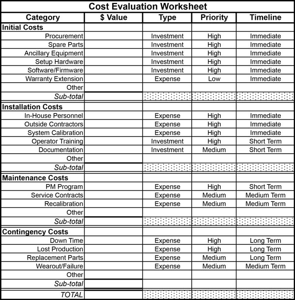
For a simple position measuring system, the direct costs of the system are easily identified, but there will still be some latent expenses which fall into one of the four categories noted above and ought to be included in the project budget. Typically the budgeting for a simple sensing system has been done on an ad hoc basis merely by adding a sensor’s purchase cost and any ancillary equipment costs, without considering the related costs. Clearly this approach does not show the total costs of the sensing system installation. A better budgeting process would be to examine the various costs exposed in the four cost categories listed above and compile a list of identifiable costs and expenses to be totalized as true cost.
For a more complex system, a careful examination of the various costs, and in particular a risk analysis pertaining to possible contingencies, can not only help in developing a more careful budgeting process, but also to head off problems resulting from unforeseen future expenses. As noted above, compiling a list of identifiable costs and expenses based on the four cost categories will aid in arriving at a true cost.
For each company or user putting a measuring system together, the true expenses or costs attributable to the various actions identified in the four cost categories above will normally vary based on local labor costs, logistics expenses, engineering rates, and management priorities, in addition to the direct costs. Thus, there is no universal chart or spreadsheet to use as a reference cost guide. For engineers tasked with developing a budget for a sensor-based measuring system, helpful guidance regarding labor rates and other expenses may often be obtained from the company’s cost accounting personnel. And if only limited ability exists to judge how much effort is required for a sensor installation or calibration, it is reasonable to get an estimate or quotation from a third party with experience in performing such tasks.
Regardless of how the true cost of ownership (TCO) is obtained, that information is very important for making the selection of the appropriate position sensor technology to be used in the measuring system.
Harold G. Schaevitz is CEO and president of Alliance Sensors Group, a division of H.G. Schaevitz, LLC.