
Alliance Sensors Group, a div of H. G. Schaevitz LLC, Moorestown, NJ, USA, makes position sensors utilizing Linear Variable Inductance Transducer (LVIT) technology which offer analog outputs of both voltage and current loop, the most common of which are 0 – 10 Volts DC and 4 – 20 mA DC. A voltage output is typically used in applications that have a receiving device, i.e.: PLC, DAQ system, or readout, located close by so the interconnecting wiring is not very long and can be shielded if necessary to prevent noise or EMI being coupled into the output.
A current loop consists of a 4-20 mA transmitter, a receiver with a loop load resistor across its input, the loop DC power source, and the interconnecting wiring for all these devices wired in series. ASG products with current loop output are 3-wire sourcing transmitters, whereby the loop and transmitter power comes from outside the loop but they share a common ground within the current loop.
There are several significant advantages to using a 4-20 mA DC current loop to transmit data over long lines from a sensor to a DAQ or control system instead of a voltage output. First of all, the current in the loop originates from a low source impedance, so the signal is much less susceptible to induced noise and electromagnetic interference (EMI) than any voltage signal. Current loop wiring typically can use twisted pair cables which often don’t require shielding. Second, there is no degradation of the signal or losses over long connecting lines from line resistance, which will happen with a voltage signal. Third, it is usually possible to insert some other current-sinking device for example, a local current readout, into a current loop by simply connecting it in series within the loop.
A major benefit of a 4-20 mA output is the “live zero” at the 4 mA point (0% of the measured quantity) so the loss of a current, i.e.: 0 mA, would indicate a malfunction in the loop, typically a break in the wiring or a disconnected device, and thereby is a fail-safe system diagnostic. Furthermore, an out-of-range loop current lower or higher than some specified value would indicate a malfunction in the system’s electronics, providing an additional system diagnostic.
Using current loop output requires more care overall than a voltage output ordinarily would. 3-wire transmitters are current sourcing, which means they drive current into the loop using DC power coming from the transmitter, so they must always connect to a sinking receiver input, where a loop load resistor is the only element involved; there is no DC power available from the input terminals of the receiving device. It is very important to never connect a 3-wire transmitter to a receiver input configured to work with a 2-wire or loop-powered transmitter because the 3-wire transmitter may be seriously damaged.
For any specified loop voltage, there is a maximum loop resistance that will permit full current to be developed in the loop. Exceeding the maximum loop resistance, which always includes the resistance of the field wiring, prevents the system from driving the full 20 mA (or higher) current into the loop. The loop load graph for a typical 3-wire current loop output sensor is shown in Figure 1. At 24 Volts input, the recommended power supply for ASG sensors and modules, the total loop resistance can be as high as 850 Ohms.
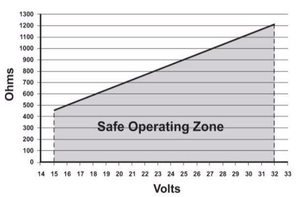
Figure 1 Maximum loop resistance vs. input voltage for a typical 3-wire current loop.
Loop load resistance is usually dependent on what voltage the receiver system input requires for good resolution. A 4-20 mA loop current will develop 2-10 VDC across a 500 Ohm load resistor (E = IR). If the receiver system works satisfactorily with a lower input voltage, a 4-20 mA loop current will develop 1-5 VDC across a 250 Ohm load resistor. Both are common loop loads that are often built into the receiving device’s input terminal connections.
The loop load resistor power rating and its temperature coefficient must be chosen to ensure that any heating caused by current flowing through the resistor does not change the resistor's value and thereby change the voltage developed across it. For a 500 Ohm loop load resistor, the power dissipated at 20 mA is 0.2 W (P = I2R). A good choice for the load resistor's power rating is at least 2 watts, preferably 3 Watts. The resistor will not heat up much, even at full 20 mA loop current, so there shouldn’t be any voltage change across the load resistor due to its power dissipation instead of loop current changes.
Connecting a 4-20 mA current meter directly to a sensor’s current output terminals is a poor practice which is to be discouraged, but a feature of ASG’s current loop output sensors is that they are capable of operating with a current shunt across their output. They will survive and continue to operate with what effectively amounts to a short circuit across their current output.
As noted earlier, the lack of current in the loop is a self-diagnostic that indicates interruption of the series loop. The most likely causes are a disconnected loop device, a break in the loop wiring, or a blown fuse in the DC power supply. It is also possible that a loop device failed in an open-circuit mode. If the loop current drops to a non-zero value below 3.6 mA, it suggests a failure in either the transmitter, the loop power supply, or the loop load resistor. If the loop current were to rise above 20.5 mA, the cause is likely to be a transmitter short circuit failure.