






How do Absolute and Ratiometric Input AC-LVDT Signal Conditioners Differ?
This is a question that comes up quite often. The answer is misunderstood by many LVDT users, so this paper will try to minimize possible confusion about absolute vs. ratiometric input LVDT operation.
How does an LVDT work?
LVDT is the acronym for Linear Variable Differential Transformer. As a transformer, it has a copper wire winding for a primary and two identical secondaries arranged in a particular geometry, which in an “absolute input” LVDT configuration are connected up in series opposition. When audio frequency alternating current passes through the primary winding, the magnetic flux created is coupled to the secondaries by a high-permeability movable armature called a core, as shown in Figure 1.
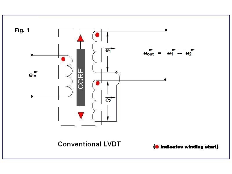
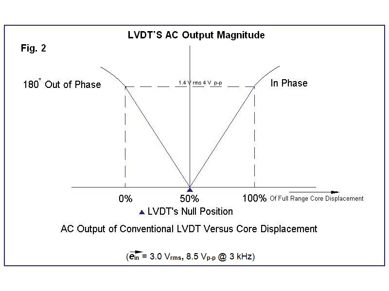
Note that the plot of its AC output amplitude versus position shows the classical “V” shape commonly associated with an LVDT, with a null voltage at the center of its range of motion, and an increase in output amplitude for core positions on either side of null. The phase relationship of the differential AC output to the primary input voltage shifts abruptly by 180° as the core moves through the null, which permits a user to know on which side of null the core is positioned. The voltage and frequency shown are typical of those found in the operation of a conventional LVDT.
The primary current, which develops the flux, usually comes from supplying a constant AC voltage called the excitation to the winding. From Ohm’s law for AC circuits, this current is a function of the excitation voltage E and the impedance Z of the primary winding at the LVDT’s excitation frequency:
I = E / Z
The impedance Z of the primary is the vector combination of two factors: a) the inductive reactance X of the primary winding, which depends on its inductance L as well as on the excitation frequency f:
X = 2πfL
and: b) the resistance R of the copper wire in the primary winding, which is independent of excitation frequency. These two factors, X and R, combine as the square root of the sum of their squares:
Z = √(X² + R²)
It is important to note that the actual excitation voltage utilized has little effect on an AC-LVDT’s performance when compared to utilizing the correct excitation frequency for proper LVDT operation.
A typical LVDT signal conditioner provides low voltage AC primary excitation for the LVDT, transfers its differentially-connected secondaries’ AC output into a synchronous demodulator which provides a DC voltage output, the polarity of which depends on the phase of the LVDT’s output compared to its primary excitation, amplifies this DC voltage, and then scales the output as required by the user. This is the ordinarily used measurement configuration known as “absolute input” LVDT signal conditioning, which is sometimes referred to as “absolute output” LVDT configuration.
The advantage of the “absolute input” AC-LVDT signal conditioning configuration is that it works with any LVDT. It is also possible to use such an LVDT signal conditioner with inductive half-bridge sensors, as can be found in gaging probes and certain position sensors used in the power generation industry if the primary excitation is offered as a push-pull drive with a single-ended grounded LVDT signal input. It also only requires either 3, but typically 4, I/O connections to the LVDT for proper operation.
How does temperature affect an LVDT?
While the resistance of the copper wire in the primary winding is unaffected by frequency, it is directly proportional to temperature, so increased temperature means increased resistance. This change in resistance increases the primary impedance Z. With a constant excitation voltage, the primary current is reduced, as illustrated above. Because the magnetic flux in the primary is directly proportional to its current (at least up to saturation) the reduced flux causes a commensurate reduction in LVDT output voltage. The problem is that the user cannot differentiate between an LVDT’s output change due to motion of the core or an output change due to temperature effects on the LVDT.
One way to help minimize this temperature effect is to make the resistive component of the primary impedance relatively small compared to the inductive reactance component, so that its contribution to the magnitude of the primary impedance has less effect. In some cases, an increase in the excitation frequency may be helpful. It may also be possible to correct for temperature effects inside the system within which an LVDT’s output is being utilized, for example, a DCS, a PLC controller, or DAQ system, by using a separate temperature compensating input to the system from a temperature sensor located near the LVDT.
However, there are several applications, typically military/aerospace, where these efforts to mitigate the effects of temperature on an LVDT-based system can prove to be inadequate. This leads to a substantially more complicated LVDT configuration that can be more effective for minimizing ambient temperature effects on an LVDT known as a “ratiometric input” or “difference-over-sum” operation.
Ratiometric input AC-LVDT operation for temperature mitigation
Ratiometric operation of an AC-LVDT is another way to minimize temperature effects on an LVDT system over a reasonable range of ambient temperature variation. However, using ratiometric output from an AC-LVDT only works correctly if the sum of the secondaries’ AC output is constant over the full-scale travel of the LVDT’s core. Unfortunately, this isn’t necessarily the case for many commercial and legacy LVDTs often used in industrial and laboratory applications.
In this alternative LVDT signal conditioning scheme, the AC outputs from each LVDT secondary are input into the system separately and internally processed to produce both the sum of the secondary outputs and the difference of the secondary outputs as AC inputs to the signal conditioning circuitry:
Ein = (S1 − S2) / (S1 + S2)
If the LVDT was designed so the sum voltage would be constant over the range of motion of the LVDT’s core, it can be used as a reference signal for the primary flux level. This sum voltage will only change if the flux level changes. The secondaries’ difference voltage will be a composite of the core’s positional output and any primary flux variations that occur because of temperature. By using the secondaries’ sum voltage as a reference in a ratiometric measurement, if the flux level is reduced because of a primary impedance increase, the sum voltage will go down proportionally, mitigating system output changes due to ambient temperature change because the ratio will remain the same.
The key to ratiometric operation of an LVDT is that it be both mechanically and electrically designed to produce a constant sum of its secondary voltages over the range of motion of the LVDT’s core. It typically needs to be constant within at least 0.5%. Ratiometric operation also requires at least 5, and typically all 6, I/O connections, which is sometimes an undesirable technical and economic burden in applications that utilize very long cables such as power plants and industrial process control systems.
Virtually all military/aerospace LVDTs are constructed with a constant sum-of-secondaries output, but many commercial and legacy LVDTs are designed for maximum output with good linearity specs, so they are constructed to favor that choice. Because ratiometric operation is the rule for aerospace LVDTs and their signal conditioning hardware, some engineers have come to believe that any LVDT has a constant sum-of-secondaries output, which is how real misunderstanding about operation of LVDTs with ratiometric signal conditioners comes about. In fact, operating an LVDT which does not have a constant sum-of-secondaries output with a ratiometric input signal conditioner will very often make the overall sensor system’s output look very poor, even useless, in terms of output non-linearity.
Absolute input AC-LVDT operation
Recognizing that the advantage of the “absolute input” AC-LVDT signal conditioning configuration is it works with virtually any LVDT, ASG produces only “absolute input” LVDT signal conditioner modules. There is no requirement for a special feature in the LVDT like constant secondary sum voltage. It is also possible to use such a signal conditioner with inductive half-bridge sensors, as can be found in gaging probes and certain position sensors used in the power generation industry, when the primary excitation is offered as a push-pull drive to a single-ended grounded input, which has always been offered in ASG’s DIN-rail-mounting LVDT signal conditioning modules, including the S2A and SC-200.
LVDT SIGNAL CONDITIONING | ABSOLUTE INPUT | RATIOMETRIC INPUT |
|---|---|---|
Secondary output connections | Differential | S1 & S2 Separately |
LVDT output measurement | S1 − S2 | (S1 − S2)/(S1 + S2) |
LVDT I/O lead connections | 3 min., typically 4 | 5 min., typically all 6 |
LVDT temperature compensation | Limited | Generally Good |
Constant secondary sum required? | Never | Always |
Works with conventional LVDTs? | Very Well | Not Satisfactory |
Common LVDT applications | Industrial / Labs | Aerospace/military |