
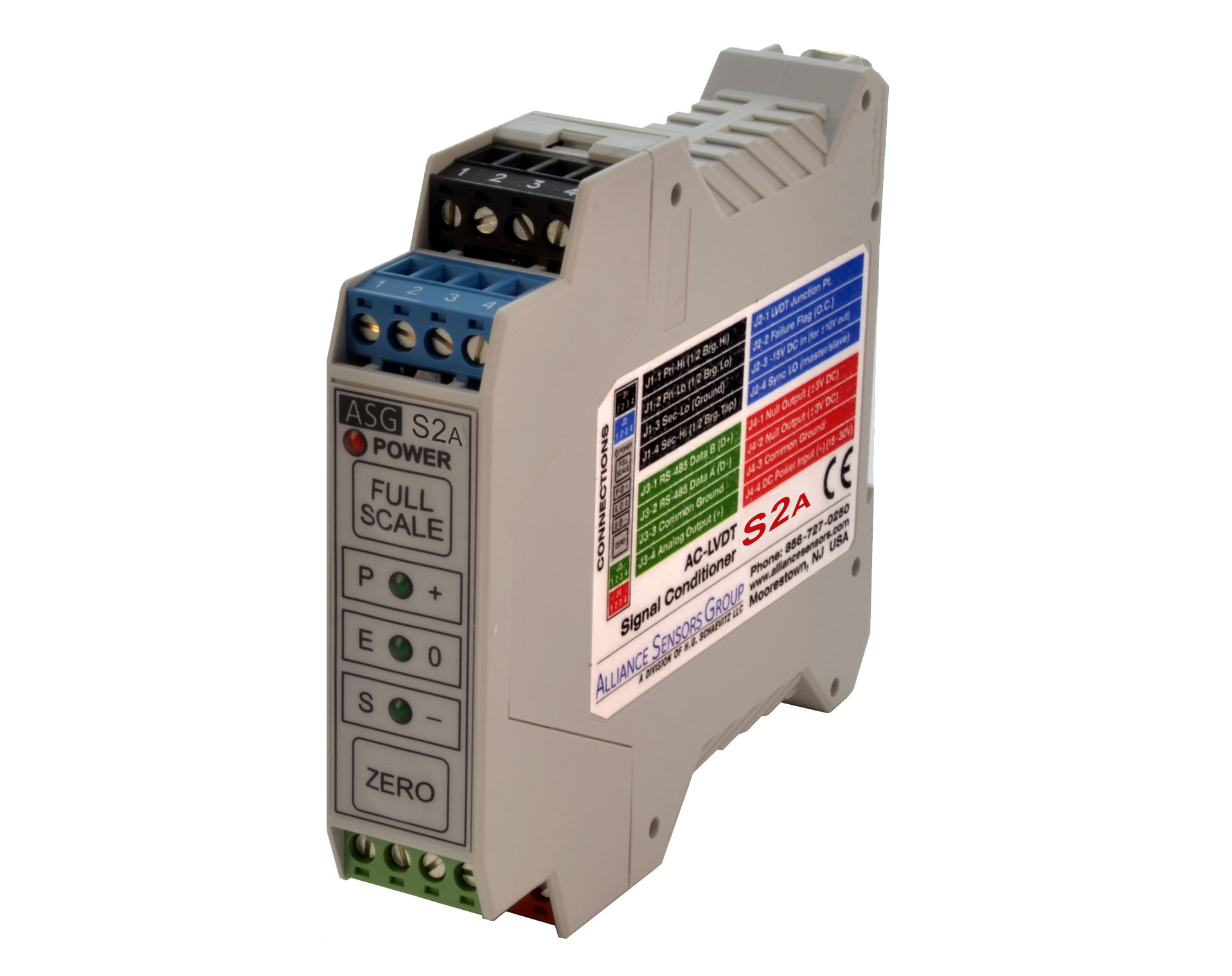
Alliance Sensors Group’s S2A DIN-rail-mounting LVDT signal conditioner is designed specifically for the power generation industry. It offers comprehensive diagnostics for sensor and wiring failure, real-time recalibration of the Full Scale and Zero outputs, enhanced ground loop noise rejection, and backward compatibility to legacy S1A signal conditioners. Utilizing front panel push buttons for easy calibration, the S2A is engineered to work with the widest range of LVDT, RVDT, and inductive half-bridge LVRT sensors by providing four excitation frequencies that will operate most AC-LVDTs over a 50 to 5,000 mVrms range of sensor output. S2A modules offer a choice of 8 analog outputs and half-duplex RS-485 digital communications to facilitate remote setup and for saving a module's setup parameters to hot swap them with another module.
Technical datasheets and additional information can be found below.
- - Cybersecurity Lock to Prevent Tampering
- - Smart Calibration by Front Panel Push Buttons -- No Pots, No Calculations
- - Color-Coded Detachable Terminal Plugs
- - Real-Time Recalibration
- - Comprehensive Diagnostics
- - Null Detection LEDs
| Operating Power: | +15 to +30 V DC (+24 V nominal), 100 mA max. at 24 V DC; +15 V DC and -15 V DC needed for ±10 V DC bipolar output |
| Excitation Voltage: | 3.0 Vrms (nominal) push-pull drive (factory default), 4.5 Vrms (nominal) push-pull drive (jumper J7 removed), 1.5 Vrms (nominal) single-ended drive for low impedance primary |
| Excitation Frequencies: | 1 kHz, 3 kHz, 5 kHz, 10 kHz (nominal) |
| Auto-Master Syncing: | Master output couples up to fifteen units; if original master fails, new master is automatically generated for fail-safe excitation control. |
| LVDT Output Range: | 50 mVrms to 5000 mVrms at LVDT’s full scale position |
| Analog DC Outputs: | 0 - 5 V, 1 - 5 V, 0.5 - 4.5 V, 0.5 - 9.5 V, 0 -10 V, -10 to +10 V, 0 -20 mA sourcing (3-wire), 4 -20 mA sourcing (3-wire) |
| Loop Resistance: | 850 Ohms maximum with 24 V DC supply |
| Output Non-Linearity: | ≤±0.025% of Full Span Output (FSO) |
| -3 dB Response: | 10% (minimum) of excitation frequency (normal setting); 10 Hz (default) user adjustable (low noise setting) |
| Noise and Ripple: | ≤1 mVrms (voltage output), or ≤2 μArms (current output) |
| Fault Detection: | Open or shorted LVDT winding, open, shorted, or grounded LVDT connection, LVDT cable disconnected, open or shorted analog output |
| Failure Indications: | Flashing LEDs; analog output driven out of range; 50 mA open-collector switch, user settable to NC (default) or NO |
| Null Detection: | Front panel LEDs; ±3V DC max. floating null output signal |
| Operating Temperature: | -20 to 75 C |
| Temperature Coefficient: | ±0.002% of FSO/C (combined span and zero shift) |
| Zero Set: | Front panel push button or RS-485 ASCII command |
| Full Scale Set: | Front panel push button or RS-485 ASCII command |
| Digital Interface: | RS-485 2-wire multi-drop network, 16 addresses |
| Cybersecurity Lock : | User enabled |
 Download the S2A Signal Conditioner Datasheet
- Download Comparison S2A to S1A Signal Conditioners
- Download The Differences Between the S2A and SC-200 Signal Conditioner
- Download S2A/SC-200 vs Competition - Signal Conditioner
- Download EU EC Declaration of Conformity S2A Signal Conditioner
- Download LVDT Signal Conditioner S2A Manual
S2A DIN-Rail Mounted LVDT Signal Conditioner Module
Advanced Smart AC LVDT Signal Conditioning for Power Generation, Turbine Control, and Industrial Automation
Product Overview
The S2A DIN-Rail Mounted LVDT Signal Conditioner Module from Alliance Sensors Group is a high-performance, field-configurable solution designed to deliver precise, stable, and reliable signal conditioning for AC LVDT position sensors. Engineered for demanding industrial environments—especially power generation and turbine control applications—the S2A provides advanced functionality, intuitive setup, and exceptional measurement accuracy in a compact DIN-rail form factor.
Purpose-built for critical applications such as steam valve position feedback, governor and throttle valve monitoring, and turbine control systems, the S2A ensures that LVDT sensor signals are accurately converted into usable analog outputs for control, monitoring, and automation systems.
Designed for Power Generation and Critical Control Applications
The S2A is specifically engineered for use in high-reliability environments, including:
- Steam turbine valve position feedback
- Governor and throttle valve monitoring
- Interceptor and stop valve control
- Boiler feedwater pump systems
- Power plant turbine control systems
In these applications, precise and dependable position feedback is essential for safe and efficient operation. The S2A delivers the stability, accuracy, and diagnostic capability required for mission-critical systems.
Advanced AC LVDT Signal Conditioning
The S2A provides complete signal conditioning for AC-operated LVDT sensors, including excitation, demodulation, scaling, and output conversion. It supports a wide range of LVDT input signals:
- LVDT input range: 50 to 5000 mVrms at full scale
Excitation options include:
- 3.0 Vrms push-pull drive (default)
- 4.5 Vrms push-pull drive (jumper selectable)
- 1.5 Vrms single-ended drive for low impedance primaries
Selectable excitation frequencies provide compatibility with a wide range of LVDT sensors:
- 1 kHz, 3 kHz, 5 kHz, and 10 kHz nominal
This flexibility ensures seamless integration with existing LVDT installations and allows optimization for specific sensor characteristics.
Flexible Analog Output Options
The S2A supports a broad range of configurable analog outputs, making it suitable for virtually any control or monitoring system:
- Voltage outputs:
- 0–5 V
- 1–5 V
- 0.5–4.5 V
- 0.5–9.5 V
- 0–10 V
- ±10 V
- Current outputs:
- 0–20 mA (3-wire)
- 4–20 mA (3-wire)
With loop resistance up to 850 ohms at 24 VDC, the S2A can support long-distance signal transmission while maintaining signal integrity.
High Accuracy and Low Noise Performance
The S2A is designed to deliver precise and stable measurement performance:
- Output non-linearity: ≤ ±0.025% of full span output (FSO)
- Noise and ripple: ≤ 1 mVrms (voltage), ≤ 2 µArms (current)
- Temperature coefficient: ±0.0025% FSO per °C
These specifications ensure high-resolution, low-noise output signals, making the S2A ideal for applications requiring accurate and repeatable position feedback.
Smart Calibration and User-Friendly Setup
The S2A features intuitive front-panel controls that simplify installation and configuration:
- Push-button zero and full-scale calibration
- Real-time recalibration capability
- Auto-mastering functionality
- Color-coded screw terminal plugs for easy wiring
These features significantly reduce setup time and eliminate the need for complex calibration procedures.
Advanced Diagnostics and Fault Detection
To support reliable operation in critical systems, the S2A includes comprehensive diagnostic capabilities:
- Detection of shorted, open, or disconnected LVDT primaries
- Detection of grounded or faulty secondary windings
- Output fault detection, including voltage shorts and current loop opens
- Installation and setup error detection
Fault conditions are indicated via front panel LEDs, and output signals can be driven out of range or switched via open-collector outputs to alert control systems.
Digital Communication and Networking
The S2A includes an RS-485 digital interface for advanced control and monitoring:
- 2-wire multi-drop network capability
- Support for up to 16 individual device addresses
- ASCII command interface for configuration and calibration
This enables integration into networked control systems, allowing centralized monitoring and configuration of multiple signal conditioning modules.
Auto-Master Syncing for Multi-Channel Systems
For applications requiring multiple LVDT inputs, the S2A supports auto-master synchronization:
- One master unit can control up to 15 slave units
This ensures synchronized excitation and consistent performance across multi-channel measurement systems, which is particularly important in turbine and valve control applications.
Cybersecurity and System Protection
The S2A includes a user-enabled cybersecurity lock feature designed to prevent unauthorized changes:
- Protects configuration settings
- Ensures system integrity in critical infrastructure environments
This feature is especially valuable in power generation and industrial systems where configuration integrity is essential.
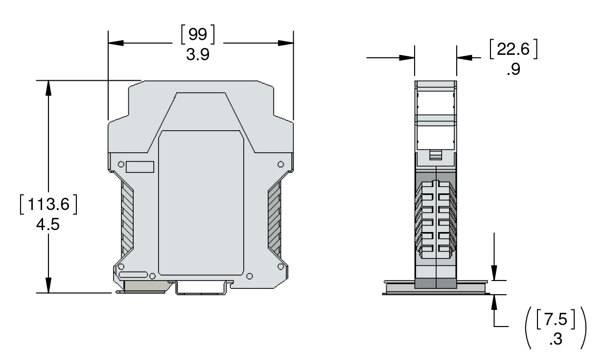
Industrial-Grade Design and Environmental Performance
The S2A is designed for reliable operation in industrial environments:
- Operating temperature: –20°C to +75°C
- DIN-rail mounting for standard industrial panels
- Robust electrical and mechanical design
Its compact footprint and rugged construction make it ideal for installation in control cabinets and industrial enclosures.
Power Requirements
The S2A operates from a standard industrial power supply:
- Input power: +15 to +30 VDC (24 VDC nominal)
- Maximum current draw: 100 mA at 24 VDC
For bipolar output configurations (±10 VDC), both +15 V and –15 V supplies are required.
Typical Applications
The S2A is ideally suited for:
- Steam turbine valve position feedback
- Power generation control systems
- Industrial automation and process control
- Hydraulic actuator position monitoring
- Multi-channel LVDT measurement systems
Its combination of accuracy, flexibility, and diagnostic capability makes it a trusted solution in high-performance industrial environments.
Summary
The S2A DIN-Rail Mounted LVDT Signal Conditioner Module provides a complete, high-performance solution for AC LVDT signal conditioning. With flexible output options, advanced diagnostics, smart calibration features, and robust industrial design, it delivers reliable and precise position measurement in even the most demanding applications.
Whether used in power generation, turbine control, or industrial automation, the S2A ensures that your LVDT sensors provide accurate, stable, and actionable data.