
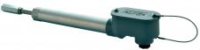
Alliance Sensors PG Series LVDT linear position sensors are designed and engineered specifically for steam turbine valve position control system applications in electric power plants. Many of the features incorporated in the design were actually requested by power generation controls engineers. PG sensor models include the PGHD Heavy Duty LVDT and the PGSD Super Duty LVDT. Both PG versions are available on special order as mild radiation resistant for operation in BWR nuclear power plants.
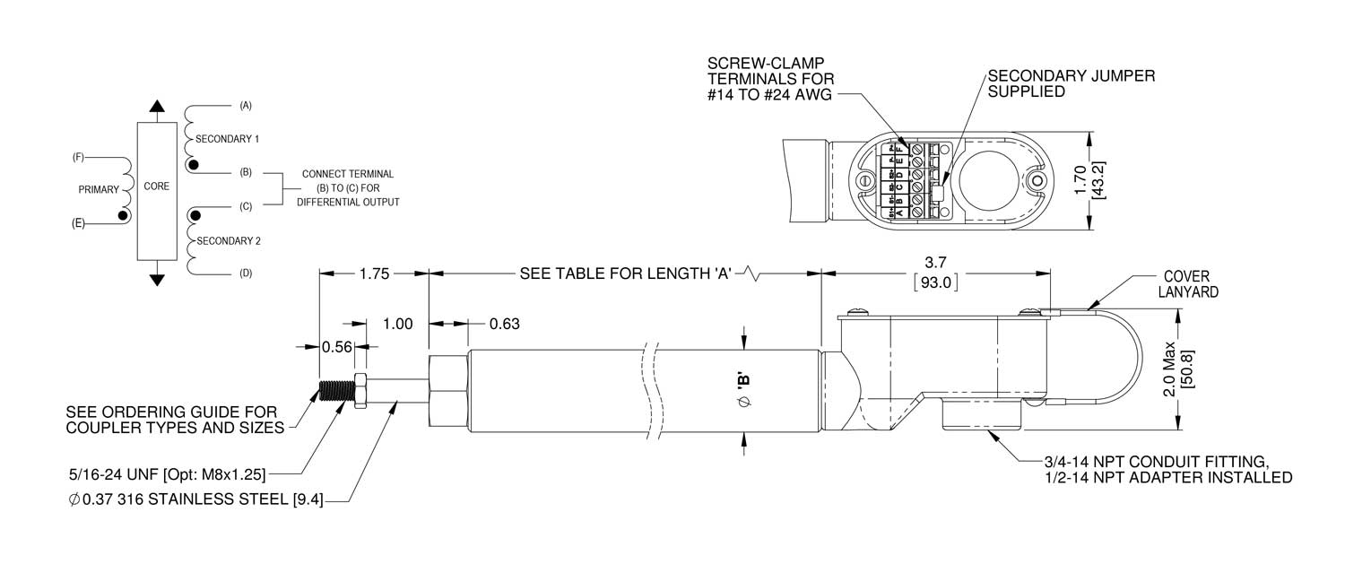
The PG Series LVDT linear sensors are heavy duty, from the wire connection terminal block inside an IP-68 sealed heavy wall housing to the 3/8 inch outside diameter core rod in which the LVDT core is encased so that it can never vibrate loose or break off. A pair of double contact shaft seals for the core rod keep dirt and water out of the sensor’s bore. An in-line ball joint coupling on the core connecting rod to take up minor installation misalignment is optionally available, along with other installation hardware such as hold-down clamps, threaded core extension rods, swivel rod eye ends, and mounting flanges. Electrical connections utilize a screw-clamp terminal block for 24 to 14 AWG wires that feed through a 3/4 inch conduit hub outfitted with a 1/2 inch conduit adapter. User-installable connectors are available.
- - Core is Enclosed in 3/8 Inch (9.5 mm) Diameter Rod...Cannot Vibrate Loose or Break Off
- - Dual Redundant Double Contact Shaft Seals Keep Contaminants out of LVDT’s Bore
- - Works in 3-Wire, 4-Wire, 5-Wire, 6-Wire, and Ratiometric (A-B)/(A+B) Systems
- - Operates to 350°F (175 C) with Over-Temperature Indicator Built in
- - Screw-Clamp Terminal Block Accepts 24 to 14 AWG Wires
- - 2 Year Warranty...Twice the Industry Standard
| Excitation Frequency: | 3 kHz nominal (Primary Z: 600 Ohms ±10%) |
| Excitation Voltage: | 3 V ACrms nominal |
| Full Scale Output: | 0.83 ±10% V ACrms output (nom.) from differentially connected (S1-S2) secondaries with 3 Vrms excitation; sum of secondaries output is constant over range for ratiometric (S1-S2)/(S1+S2) operation |
| Linearity Error: | ±0.5% of FSO max. |
| Operating Temperature: | -40 to 175 C (-40 to 350 ̊F) |
| Temperature Coefficient: | ≤±0.025% FSO/degree C |
| Shock: | 1000 g, 11 msec. |
| Vibration: | 5-20 Hz, 0.5 inch p-p; 20-2000 Hz, 4.2 g p-p |
Model | Version | Operating Range | Coupler Type | Rod Coupler Size * |
PG | XX- | XXXX- | XX | (XXX) |
| HD Heavy Duty | 0203 2 to 3 inches | BJ Ball Joint | 6XL 3/8-24, 1 inch deep (3.5" OA) (Ball Joint and Rigid Nut Coupling) |
| SD Super Duty | 0406 4 to 6 inches |
|
|
|
| 0609 6 to 9 inches |
|
|
|
| 0912 9 to 12 inches | RN Rigid Nut | 6L 3/8-24, 3/4 inch deep (1.75" OA) (Rigid Nut coupling only) |
|
| 1215 12 to 15 inches |
| 6XL 3/8-24, 1 inch deep (3.5" OA) (Ball Joint and Rigid Nut Coupling) |
|
| 1216 12 to 16 inches |
|
|
|
|
|
|
|
|
|
|
| * No size callout gets 6XL default |
Model No. | Linear Range | Body Length ‘A’ | |
PGXX-0203 | 3.00 INCHES | 6.50 INCHES | 165.1 MM |
PGXX-0406 | 6.00 INCHES | 10.25 INCHES | 260.4 MM |
PGXX-0609 | 9.00 INCHES | 13.25 INCHES | 336.6 MM |
PGXX-0912 | 12.00 INCHES | 17.25 INCHES | 438.2 MM |
PGXX-1215 | 15.00 INCHES | 21.25 INCHES | 539.8 MM |
PGXX-1216 | 16.00 INCHES | 21.25 INCHES | 539.8 MM |
Model | Body Diameter ‘B’ | Hex C | |
PGHD | 1.05 INCHES [26.7 MM] | 0.937 Inches [23.8 MM] | |
PGSD | 1.32 INCHES [33.5 MM] | 1.125 Inches [28.6 MM] |
If you are looking for CAD drawings of our PG Series sensor, simply call us at 856-727-0250 or use the online contact us form by clicking here.
How Precision Valve Position Monitoring Prevents Catastrophic Turbine Failures
In power generation facilities, steam control valve positioning represents a critical safety and efficiency parameter that directly impacts grid stability. AC-LVDT linear position sensors designed specifically for steam valve applications provide the accuracy, reliability, and response speed necessary to prevent turbine overspeed conditions, optimize heat rates, and ensure safe plant operation. These specialized sensors withstand the extreme temperatures, vibrations, and environmental challenges unique to steam turbine environments.
The consequences of valve position measurement failure in power generation extend far beyond equipment damage. Inaccurate steam valve control can trigger turbine overspeed events, potentially causing catastrophic mechanical failure with risks to personnel safety and millions in equipment damage. Grid instability from sudden generation loss affects thousands of customers while emergency repairs create extended outages.
Understanding Steam Valve Monitoring Requirements in Modern Power Plants
Power generation engineers face unique challenges when specifying position sensors for steam control applications. Operating temperatures near valves routinely exceed 500°F, while steam leaks create 100% humidity environments that destroy conventional sensors. Continuous vibration from turbine operation demands exceptional mechanical durability.
Modern combined-cycle plants operate with tighter efficiency margins than ever before. Heat rate optimization requires valve position accuracy within 0.1% to maintain competitive generation costs. Load-following operations subject valves to thousands of positioning cycles monthly, accelerating wear on mechanical linkages.
Critical Safety Functions and Regulatory Compliance
Steam valve position sensors serve multiple safety-critical functions beyond simple control feedback. Turbine protection systems rely on accurate valve position data to initiate emergency trips during overspeed conditions. Regulatory compliance documentation requires continuous position recording for post-incident analysis.
Integration with Distributed Control Systems
Modern power plants utilize sophisticated distributed control systems (DCS) for coordinated operation. AC-LVDT sensors provide industry-standard 4-20mA outputs compatible with all major DCS platforms. Digital HART communication options enable remote diagnostics and calibration verification without entering hazardous areas.
Design Features Essential for Steam Valve Applications
Successful steam valve position monitoring demands specialized sensor construction. Heavy-wall stainless steel housings resist corrosion from steam chemistry while maintaining dimensional stability across temperature extremes. Welded construction eliminates potential leak paths that compromise sensor integrity.
High-temperature coil designs utilize specialized insulation systems rated for continuous 750°F exposure. Ceramic bushings maintain precise alignment despite thermal cycling. These materials prevent the signal drift and mechanical binding that plague standard sensors in high-temperature service.
Installation Considerations for Reliable Long-Term Operation
Proper installation proves critical for achieving expected sensor lifespan in steam valve applications. Mounting brackets must accommodate thermal expansion without inducing mechanical stress. Flexible conduit connections prevent vibration transmission while maintaining environmental seals.
Heat shielding strategies protect sensors from direct steam impingement during valve packing leaks. Reflective barriers and insulation blankets maintain sensor body temperatures within design limits. Strategic mounting positions minimize exposure while maintaining mechanical coupling integrity.
Linkage Design and Mechanical Coupling
Converting rotary valve motion to linear sensor displacement requires robust linkage systems. Hardened pins and bushings resist wear from continuous operation. Anti-rotation features prevent linkage binding while accommodating misalignment from thermal effects.
Regular linkage inspection identifies developing wear before measurement accuracy degrades. Scheduled bushing replacement during routine valve maintenance prevents unexpected sensor failures. Proper lubrication extends component life in high-temperature environments.
Preventive Maintenance Programs for Maximum Reliability
Steam valve position sensors require minimal maintenance when properly specified and installed. However, implementing preventive maintenance programs identifies developing issues before failures impact plant operation.
Quarterly calibration verification ensures measurement accuracy remains within specifications. Comparing sensor outputs to physical valve positions reveals linkage wear or sensor degradation. Trending calibration data predicts remaining service life for planned replacement scheduling.
Common Failure Modes and Troubleshooting
Understanding typical failure mechanisms accelerates problem resolution. Signal drift often indicates insulation breakdown from moisture ingress. Erratic readings suggest mechanical binding or linkage wear. Complete signal loss typically results from cable damage or connector corrosion.
Systematic troubleshooting procedures isolate problems quickly. Resistance measurements verify coil integrity while voltage checks confirm power supply operation. Mechanical inspection reveals binding or excessive play in linkage systems.
Performance Validation Through Real-World Experience
Power generation facilities worldwide validate these specialized sensors' exceptional reliability. Combined-cycle plants report continuous operation exceeding 100,000 hours between failures. Nuclear facilities document 18-year service intervals with minimal calibration drift.
Coal-fired plants operating in particularly harsh environments achieve 10-year mean time between failures despite coal dust contamination and thermal cycling. Preventive replacement during scheduled turbine overhauls eliminates unplanned outages from sensor failures.
AC-LVDT linear position sensors engineered specifically for steam control valve applications provide the reliability, accuracy, and durability essential for modern power generation. Their specialized construction addresses the unique challenges of high-temperature, high-vibration turbine environments while delivering the precision necessary for optimal plant efficiency. Power generation engineers cannot compromise on valve position monitoring—these purpose-built sensors ensure safe, reliable operation protecting both equipment and grid stability.